Tinkercad + Eagle + Laser Head : first steps
A new tool to design PCB from sketches is Tinker Cad Circuits.
This software is a free and easy way to design PCB and emulate them. Together with Autodesk Eagle (free 30 days trial is available on Autodesk website) and FABtotum’s Laser Head it allows to design PCB easily.
Tinker Cad allows to export Eagle’s compatible sketches. Eagle is one of the most common softare used to for PCB making.
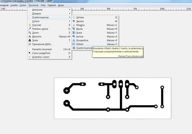
This step-by-step guide will show you how to have all the needed files from your sketch and how to convert them in order to correctly use them with FABtotum’s Laser App, the online software you received bundled with your Laser Head.
First of all, create an account on Tinker Cad circuits. Once ready, you can start realizing your sketch, by selecting your bread-board and placing all components as you can see in the sample image. In our example we will realize a simple voltage regulator (or AVR) with a LED output.
Once all components have been placed, you need to connect them with conductive wires. You should get something similar to the photo you can see next here. When all parts are correctly linked you can emulate the circuit by clicking on “Start Simulation” or clicking su “Export” – as for our example – to create the PCB. The file will be saved as .brd.
To design PCB from the saved file, open Autodesk Eagle and open the Tinker Cad Circuits downloaded file, following the path “File -> Open -> Board.


