Design and 3D print a robotic arm with fusion 360 and the FABtotum
Today we take a look at a simple but interesting project that made a few months ago. As the title implies, we designed, printed, assembled and tested a 3 axis robotic arm.
Parametric CAD and 3D printing allowed to do almost all of this in a day or so.
This is part 1 of 2. The second part comes in next week. Let’s get into it.
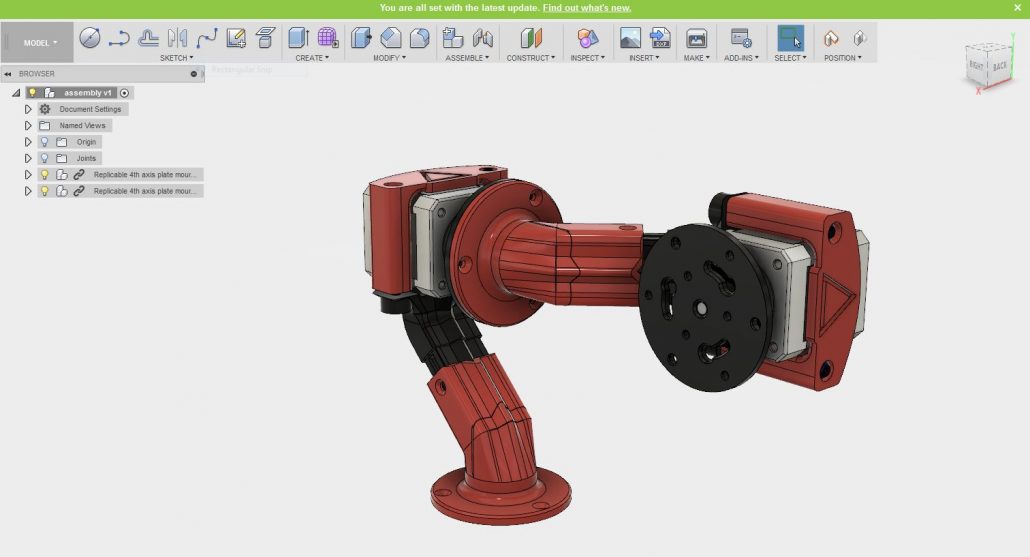
We started by designing a modular arm, one that could be printed in multiple copies and bolted to make the primary arm.
This design was first used as a proof of concept on 5 axis machining we did back in 2016.
The objective here was to create a very simple, easy to print and rigid structure that could be used for simple object manipulation.
The structure for it won’t need to be extremely stiff but we designed the arm as stiff as possible anyway.
The arm ends with the motor holder on one side (standard nema 17) and a standard FABtotum chuck on the other. So that you can have compatibilty with the 4th axis chuck we designed a few years ago. (This was designed in fusion 360 too).
With all the parts in place it was time to export them to STL and into a slicing software. For this project we used Simplify 3D, but any will do.
We filled the build platform with all the parts needed to make two axis (i.e: two arms!).
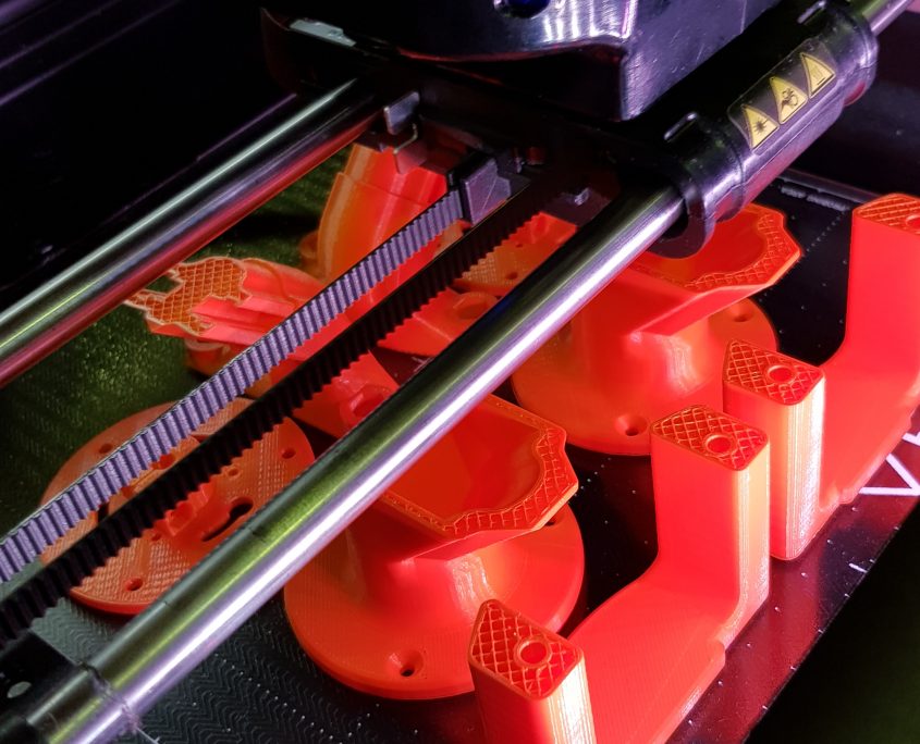
We used the Print Head Pro with our Orange PLA filament. Nothing too fancy but pleasant nonetheless, and reminescent of industrial heavy duty machinery.
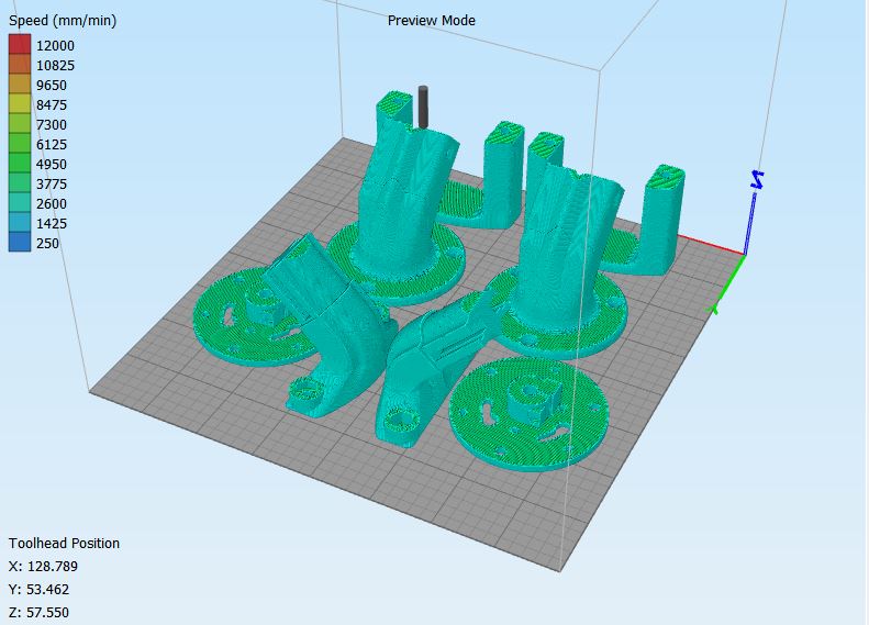
To 3D print the parts we took advantage of our small industrial cluster of FABtotum 3D Printers, a set of internet-connected units we always have ready for production, prototypes and personal projects.
We connected using the my.fabtotum.com interface and uploaded the updated design files.
The print itself was made without batch controls (all parts at the same time). This allows to use the entire build surface since parts can be as close as possible between them.
In the next images you can see the build plate extracted to show how much space was still available should we wanted to make a fourth axis as well.
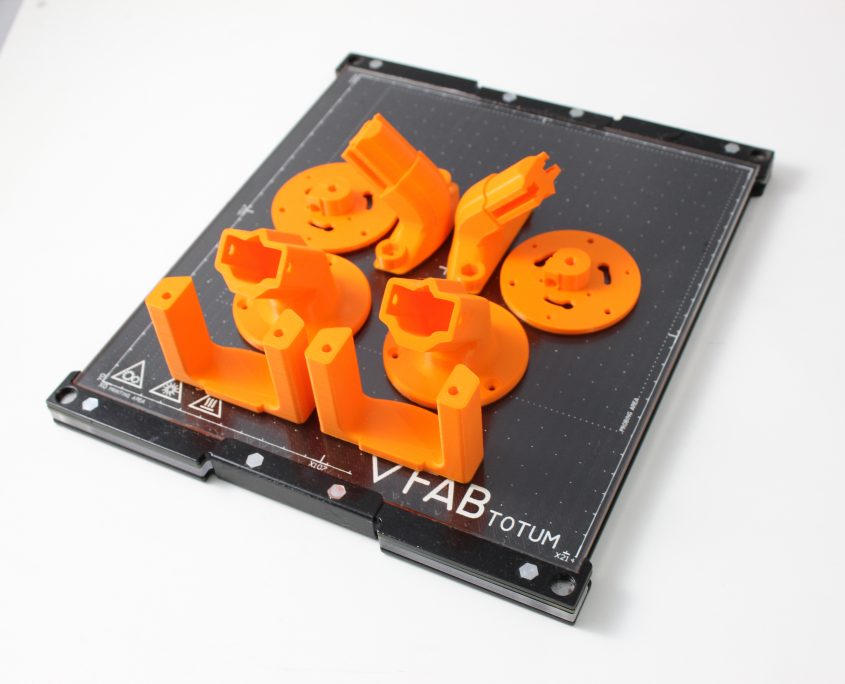
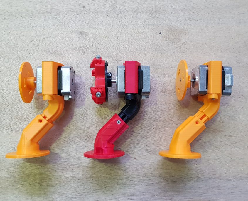
Once removed from the build plate, the parts were assembled with bolts seaparately.
On the third image of the previous row, a variant created with the 4th axis chuck attached.
The arm will be mounted on a single motor (axis A) that will rotate around the vertical axis. The other two motors will respectively lower the arm and tilt the forearm.
With those 2 orange arms assembled we proceeded bolting the two together, making the B and C axis respectively.
The range of motion of this arm isn’t comparable with 4-5 axis robots but it’s enought to do some simple pick and place of objects.
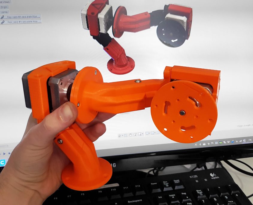
This will indeed be the application we will implement in part 2.
In Part 2 we’ll create the base and the forearm in fusion, design and build a simple electromagnet so that the arm is able to pick up metal objects from a container and deposit them in another.


