3D printing for the industry: Jigs and Fixtures
There are many uses for 3D printing in the industrial field.
One way to do so is by using directly 3d Printing, i.e. directly making parts for your products.
Another way to use 3D printing “indirectly” is as a mean of supporting manufacturing and assembly efforts in the production line.
In fact, one of the easiest ways to incorporate digital manufacturing in the production line is in fact by using 3D printed jigs and fixtures to optimize the production workflow.
3D printed Fixtures as ergonomic aids
Jigs are usually used to make other operations easy and straightforward.
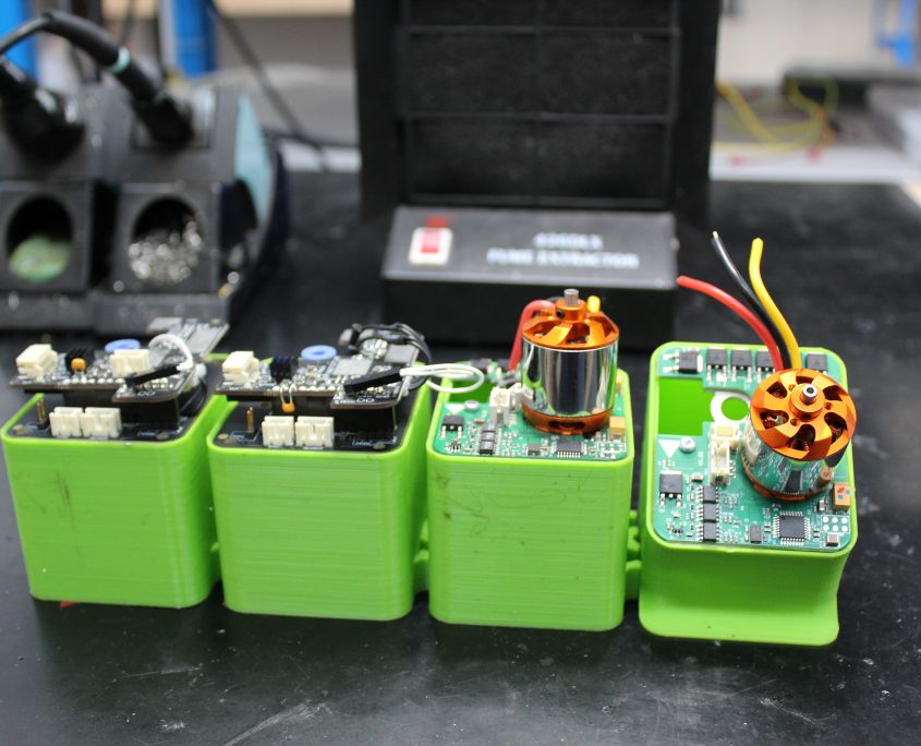
Like the example on the right (a support to allow assembly of a PCB board), jigs can be used to assist assembly or diagnostics of one particular part.
In this particular case ergonomics considerations are used to make the assebly easier by tilting the board and fixing it.
This kind of jig has a very limited design and production cost and can be made in a few hours.
The benefits of this kind of parts is measured by the amount of time is saved each time (a few seconds or minutes ) at a time, multiplied by days.
the results are several hours saved in a typical assembly line each month.
On top of that a better assembly protocol can be astablished (by presenting the part in a particular way that is easy to assemble) and thus reducing potential issues and QA defects.
3D printed Fixtures as assembly aids
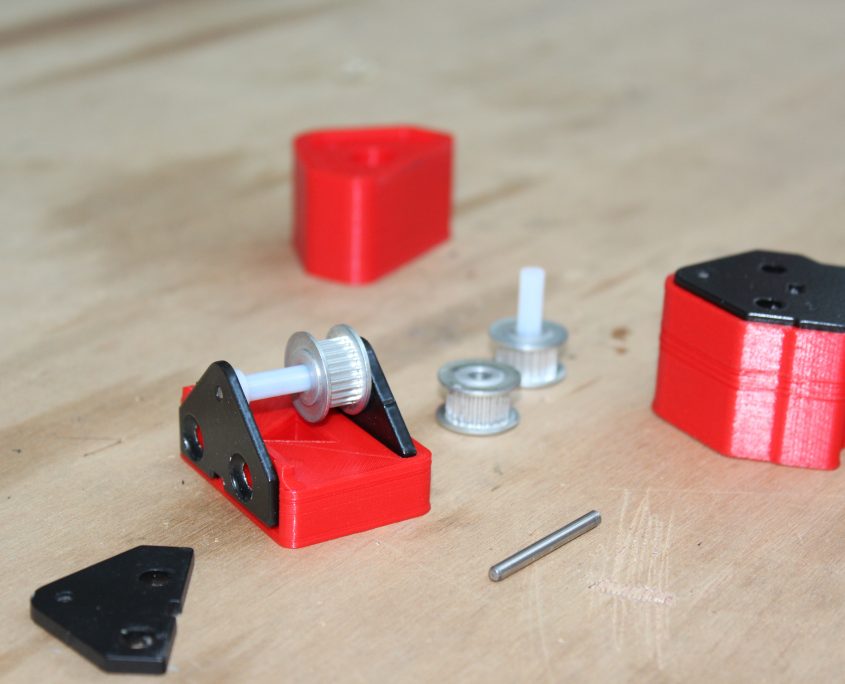
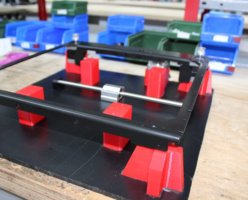
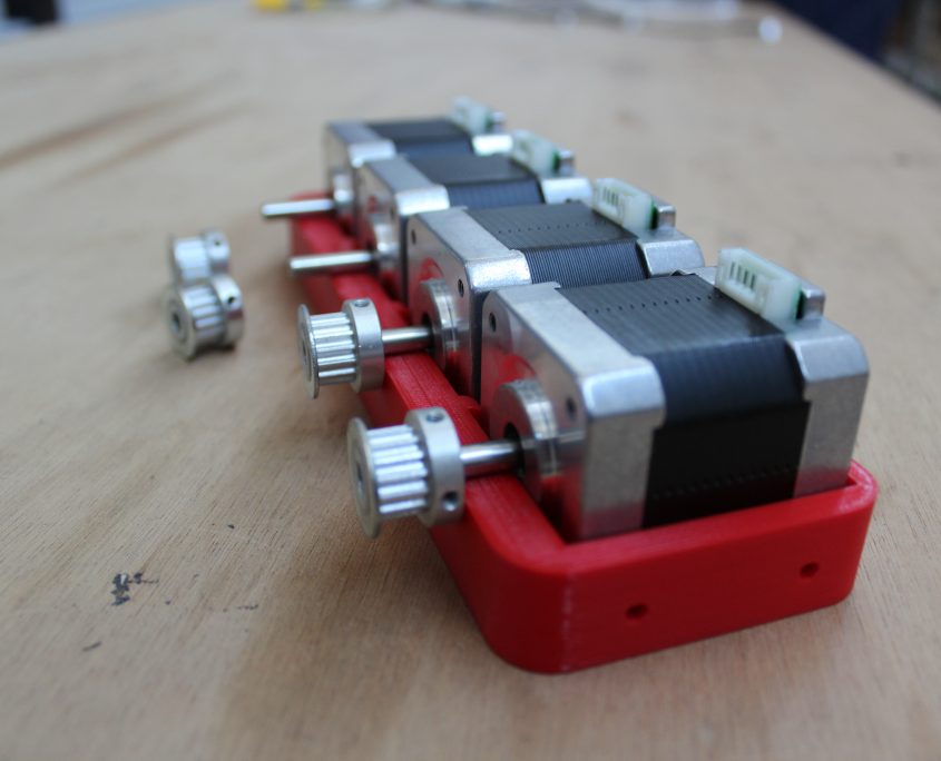
Another example is the one used as a fixture here: a support for assemblying a complex object.
A fixture is then used to place the part in place and assisting the worker in the assembly phase.
just like the other example above the main advantages are the following:
- Parts fit only their designated spots (reduced errors, misplacements)
- Quickly populate the assembly with parts (efficiency boost)
- Parts are correctly oriented,spaced and can be fastened/glued togheter with no human error. (improved precision)
Design guidelines
When designing a fixture a lot of things should be taken into consideration:
- ergonomics: how to make the fixture ergonomic to handle/use
- tolerances
- assembly procedure
Thankfully 3D printing allows to iterate multiple versions of the same jig/fixture in a matter of hours so that changes can be made.
the Jigs and fixtures projects can be saved and kept in one’s own archive to be used when needed.
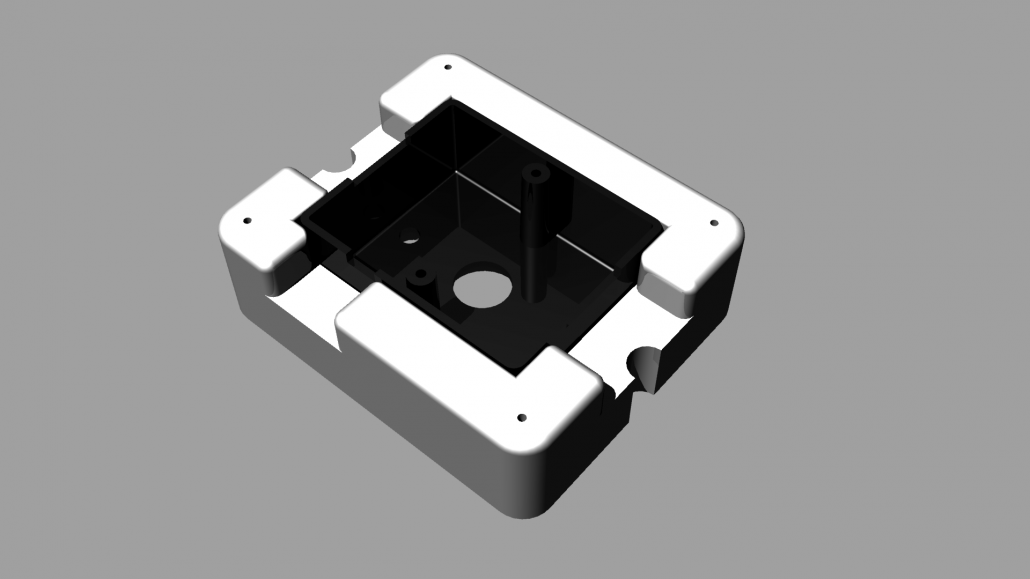
3D printed jigs for manufacturing: a case study
Jigs are used to fix the object to work on from moving relative to the tool.
In this example we’ll take a look at how design, manufacture and deploy a jig for retooling of a plastic case part.
The problem that was solved with 3D printing was to hold a piece for CNC milling on a ABS plastic case.
The Jig was created with a CAD modeling tool and tested in a CAM environment in order to plan the gcode sequence.
As a result all positions and offsets (including home position) were accounted for directly in the design phase.
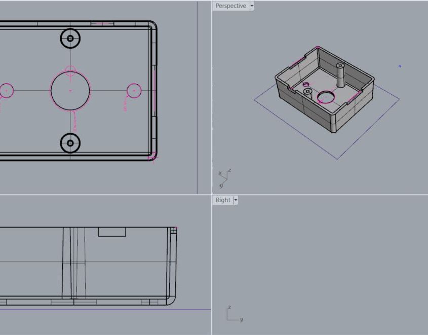
The part to be milled is positioned
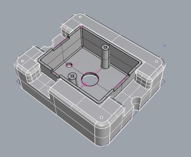
The support is designed around the part
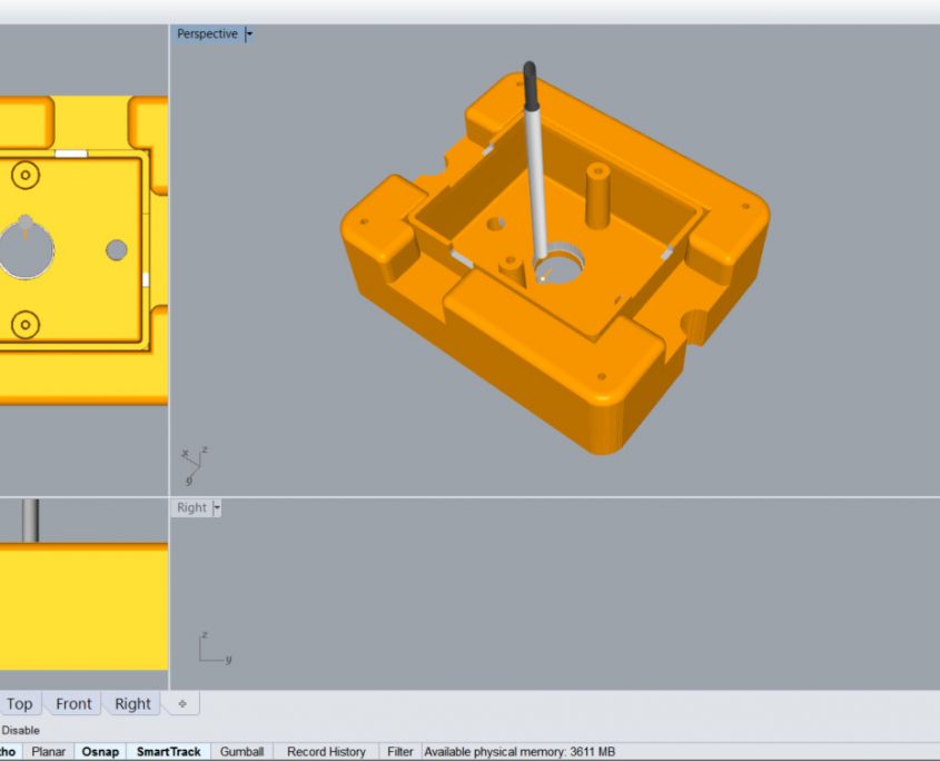
A CAM simulation can be run with the jig and part assembled.
Since the design phase is relatively quick in a CAD environment, more time can be dedicated to iterate the design phase with a physical prototype.
In this case the position of the part and the snug fit we wanted to achieve was essential for this kind of milling processes on an high number of pieces.
Finally, as the images shows, the CAM itself can be simulated with the digital design itself to keep quality,safety and usability considerations as an high priority concern.
While not this is the case in this example, The jig itself could be even considered sacrificable during certain operation, so that a part of the jig itself is milled to free the part or to reach certain spots.
