How it’s made: FABtotum Personal Fabricator
The production and release date of the Personal Fabricator has been pushed back until at least late July to account for late supplies, but that this doesn’t mean production will have to start from scratch.
The FABtotum is no simple object so a good amount of the thinkering done was targeted at the manufacturability of the product.
The FABtotum assembly line is… well, not in line, but a parallel assembly system.
Each sub assembly component has it’s own assembly area, to minimize complexity and promote specialization and productiviy. All the sub-assemblies are gathered together when and where needed to become a completed machine.
We tought it would be extremely intresting to show you how the production process unfolds.
If you are a DIY FABtotum kit backer you might as well get an idea of what are the critical procedures and what goes where. Don’t sweat too much, tough. the most complex sub assembly / components will be preassebled in the DIY kit.
If you are waiting for a fully assembled FABtotum, sit back and watch what has been done under the hood!
Head
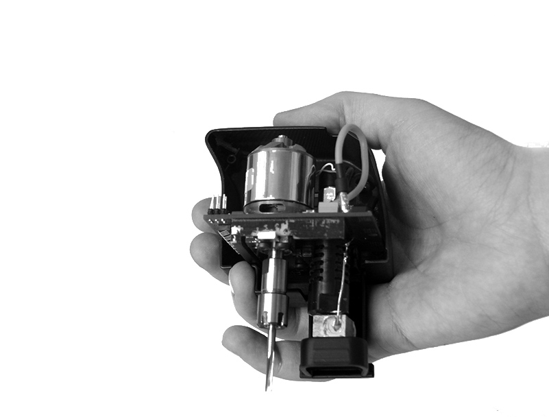
We uncovered the FABtotum’s hybrid head a couple of weeks ago, so there is plenty of information about it.
the head is composed by a few parts:
- The outer shells
- The PCB controller
- The Extruder assembly
- the 200W milling motor
While the outer shell and the controller PCB don’t require assembly or soldering, mounting the milling motor requires the unit to be disassembled and re-assembled with the er-8 motor shaft in place, then bolted to the pcb controller and an Aluminum plate.
But before locking the PCB to the aluminum plate, mounting the cooling fan and turbine, the extruder must be assembled and placed,terminals have to be soldered to the PCB with heatshrink tube in place.
Long story short, assembling the head requires each step to be performed in order, and therefore is probably the most complex part we have.
Considering the importance of the part, it will come assembled even in the DIY version, unless you feel really badass and want it your way.
X Axis Assembly
The hybrid head (as well as any possible head we’ll make) will be carried around the XY plane by the head carriage.
The head carriage is made by 2 identical, interlocking, hi-density polymer plates, with a a couple adjustable belt anchors (two because belt tensioning is needed on both sides of the belt circuit to balance tensions).
Before locking togethere the 2 parts, a couple of linear motion bearings are placed inside along with the lock mechanism and as well as the electronics placed on the carriage.
The carriage is in-fact, a platform on wich the head sits and drains power, but it also feature an LED for illuminating the working area, the laser line generator and the Z-Probe Digitizer.
The Z-probe digitizer is itself made by 3 parts: A servo motor, the probe Arm, the force sensing resistor (FSR). (above the pre-production prototype until we receive the final parts)
Once mounted, the carriage receives two 10mm linear rails, at the end of wich is mounted the X axis support.
The part, mounted like this, is bolted on the linear motion bearings on the Y axis, on the coreXY frame.
CoreXY Frame
While we were talking about the head, and the carriage, someone else was preparing the platform on wich all this tech has to be mounted precisely: the coreXY frame.
This sub-assembly is basically made of:
- An aluminum panel, lasercutted and bent to shape
- 3 nema17 motors (X,Y,Z Axis)
- 4 supports
- lots of pulleys
- approximately 2,4m of reinforced GT2-3mm belt
The procedure for this, is , despite the premise, a much more simpler task.
The shafts are mounted on the supports with the bearings in, wich are in turn bolted to the frame.
The motors are mounted on the frame as well, and the pulleys are placed in the frame.
The belt (actually 2 parts of it) is then passed on the motor pulley, straight into the X axis support, to the carriage and on the other side of the X-axis gantry as well, following the path exposed in belts and stuff, experiences to share.
ball bearing at the end of both sides of the X axis are used to guide the belt and are locked in place by the same bolt that lock the X axis assembly to the bearings on the Y axis.
In the front a LED board is mounted: this board provides RGB and ambient light inside the FABtotum Personal Fabricator and will be later connected to the “Totumduino” Control board.
Camera
The camera, wich is used for 3D-scanning and other stuff, can now be mounted on the Y axis, in particular below the left-side linear bearing.
This is a pretty straightforward process involving 3 parts.
- A standard issue RPI-Camera Module
- A longer Flex cable
- Our custom made camera casing/support
The camera is basically taken from the original box,separated from the flex cable, calibrated to focus on a specific distance instead of infinite. This is accomplished by turning the 3.5mm lens casing on top of the module.
We build a custom rig for this, as many other tools that are usefull for bending and cutting parts are made by us for the purpose of assisting the operator in precise operations.
Once calibrated the module receive the new flex cable, wich is longer than the original, and is then locked in place inside the camera casing.
the flex is then bent at specific distances to prepare it for future assembly and the module is bolted to the Y axis of the CoreXY assebly.
the coreXY assembly is now complete.
The RPI camera is well known to suffer from static shocks. Cleaning and static shock countermeasures have to be taken in to consideration, just like elsewere.
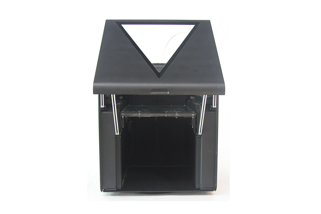
Double-face fabrication platform/heated bed
The plane/bed/platform/whatever is maker ingenuity at it’s finest.
It’s made by sticking together a PCB heater with a glass sheet, a suitable polymeric spacer and an aluminum plane.
Ingredients:
- Aluminum panel with fixtures
- PCB heater
- Glass plane
- Spacers
- locking mechanism (keeps the assembly together)
All these parts comes ready to be mounted and beside some bolts it’s a pretty simple sub-assembly.
A mask can be used to speed up the process as well, but this part is not mounted, it’s provided separately in the box to avoid damaging the part during shipping.
At the end it looks somthing like the picture above, minus the scratches we made by countless tests on cheap spray paint (all the painted parts are processed with powder coating).
A/E block assembly
The A/E block is composed by a miriad of small parts,and it’s the second most complex part in the FABtotum.
- Nema 17 motor (E Axis)
- 1:20 worm gear reduction
- Gearbox casing
- Feeder wheel
- ball bearings
The gearbox is pretty simple to mount but takes a bit of time due to the small parts and the tuning needed.
Z assembly
The Z assembly is basically the Z plane and build platform support.
To keep it simple, It’s the part that goes up and down, and It’s composed by the following parts:
- A/E block (subassembly)
- Linear bearings
- Aluminum brakets and mounting plate
- rails/shaft supports
While not part of the Z axis, the lower bottom panel is used to mount the shafts and as a mask to calibrate the Z axis during the assembly.
Once mounted the part is ready to be used as a base for completing the assembly process.
Oh and I almost forgot: silicone rubber feets are sticked under the botton panel with a mask.
Electronics
In the fabtotum the wiring and the electronics are already pre-made so the assembly process is simply connecting things and bolting the PCBs in place.
This part of the assembly is mostly carried out in the left-side of the machine, inside the 45mm deep pocket of the structural side panels, but some wiring stretches out to get to far components like the carriage (served by a flex cable) , the Led board in the CoreXY assembly and safety switches on the far side of the device.
The first thing is mounting the 24V power supply unit inside the side panel.
then we have the Totumduino board, wich is bolted in place on pillars, with an heatsink attached on the far side for heat dissipation.
On top of the board a cooling fan is mounted over the five (yes five) Allegro A4988 stepper drivers for the X,Y,Z,A/E,B axis.
All the motors and connectors are plugged in place.
the Raspberry PI is then bolted in place with his main pin header mating with the Totumduino.
Ok that sounded dirty.
There are around 6 switches that are used either for safety purposes (AKA checking the machine is not milling with the front panel open), endstops, homing switches.
At this point the side panel, containing the brain of the machine, has some connectors sticking out, ready to be united with the rest of his body.
Chassis & cover
The next step is the final assembly step.It involves connecting all the parts and using the outer shell to complete the task, as it serves strucutral purposes as well as aesthetic and safety purposes (to enclose the building area and cover all the mess behind).
The chassis is composed by:
- Front facing cover (the “main panel”)
- Top covers
- Rear cover
- Side panel
- Side panel covers
The Z axis assembly is joined to the CoreXY assembly.
The Z axis Motor is connected to the Z axis leadscrew with a closed loop belt.
the CoreXY, standing on the top, is bolted down and the mechanical core of the FABtotum is completed.
The Side Panel containing the Raspberry Pi and Totumduino Board, as well as the PSU and part of the main wiring infrastructure of the FABtotum is bolted in it’s place by using holes pre-drilled on the CoreXY frame and the Bottom panel frame.
the same is done to the other side panel, wich normally contains the filament spool within is width.
At this point all the wiring is finalized by placing snap-in adhesive clips and by conforming the wire to the narrow passages. Endstops are bolted in place and the Ledboard is connected.
the side panels are closed by adding magnetic locks, the top and back cover is locked and bolted in place (the holes are placed on the side panel, therefore this operation was possible only now and after the Z carriage is finalized!)
The last part is mounting the front cover, with his brackets and arms.
the front cover is therefore comparable to a sub-assembly itselft, with the front windows and side brackets to be mounted separately.
Software Testing, Quality Assurance
Before closing the side panel covers (wich can be opened and closed thanks to a magnetic lock) a pre-cooked 8GB SD card is inserted in the Raspberry Pi.
The card contains the OS and the Software (the FABUI) necessary to run the FABtotum.
A self test procedure involving movement and functionality is run to verify that the machine is worty :
- Extruder turn on, reach temp, turns off
- Bed turns On, reach temp, turns off
- Milling motor turns on, off, RPM stress test.
- XYZ speed test procedure.
- Carriage assembly control:
– Probe extension and retraction
– Light on/off
– Laser on/off - Test print of a sample file.
- the carriage and the Z axis are moved to a safe shipping position.
At the end the software is reset and the machine is back to factory settings ready to be packed.
Other QA procedures involve checking for the presence of defects or scratches that could occur despite precautions.
Packaging
The machine is then moved from the test bench to the packaging area.
A Moisture-Absorbing bag is placed inside the FABtotum to guard humidity during shipping.
This is pretty important since we will be start packing the FABtotum during summer, where in Milan we have usually 70-85% relative humidity at around 30°C. Yeah it’s a torture even with air conditioning.
While stored in the courier airplane cargo bay. the temperature of the air will go below dew point, causing the water content of the air to condensate, trapped inside the plastic bag. The moisure absorber is there to avoid that.
The Build platform is wrapped in bubblewrap and placed inside the FABtotum As well.
The welcome kit (including instructions and other documentation), the wifi USB dongle, the Hybrid head , the Ethernet cable, the AC cable are all wrapped in bubblewrap and stored inside the FAbtotum.
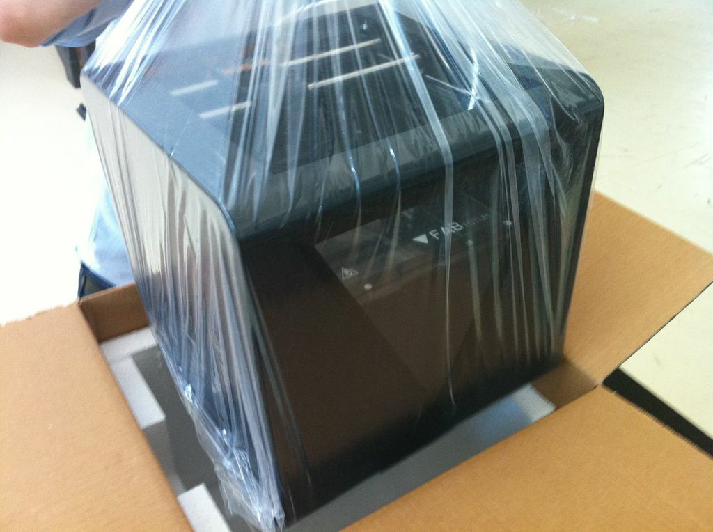
The axis are blocked in place and the machine is put in a PET transparent bag.
The shipping box is prepared and 4cm-thick estruded polystyrene shells are placed on all 6 sides, giving maximum protection.
Once the machine is placed inside, the box is closed and sealed.
Shipping
Of course each machine must get to a separate destination, and one FABtotum can be red,white or black.
A computer connected to our database assist in the final shipping procedure by creating a shipping invoice /documentation and preparing the pickup with the Express courrier.
Once the box has left our facility ur system will forward the tracking number to the provided email address.
And there you have it!
this is how a FABtotum is made.
As you can see it’s a lot of work to produce one unit, and the amount of parts,components and procedures involved is huge.
But by streamlining the assembly and simplyfying some procedures by breaking them down to sub-assemblies the production of the FABtotum personal Fabricator is a straightforward process.
As usual we are well open to suggestions and reading your feedback.
head over to the forums to leave a comment.