2014 World Maker Faire, New York

Hi guys!
We just came back from the 2014 Word Maker Faire in NYC.
As you may know we jumped in the Faire at the last moment, and we where able to get a space and organize all the logistics at the last minute. Here’s how it unfolded…

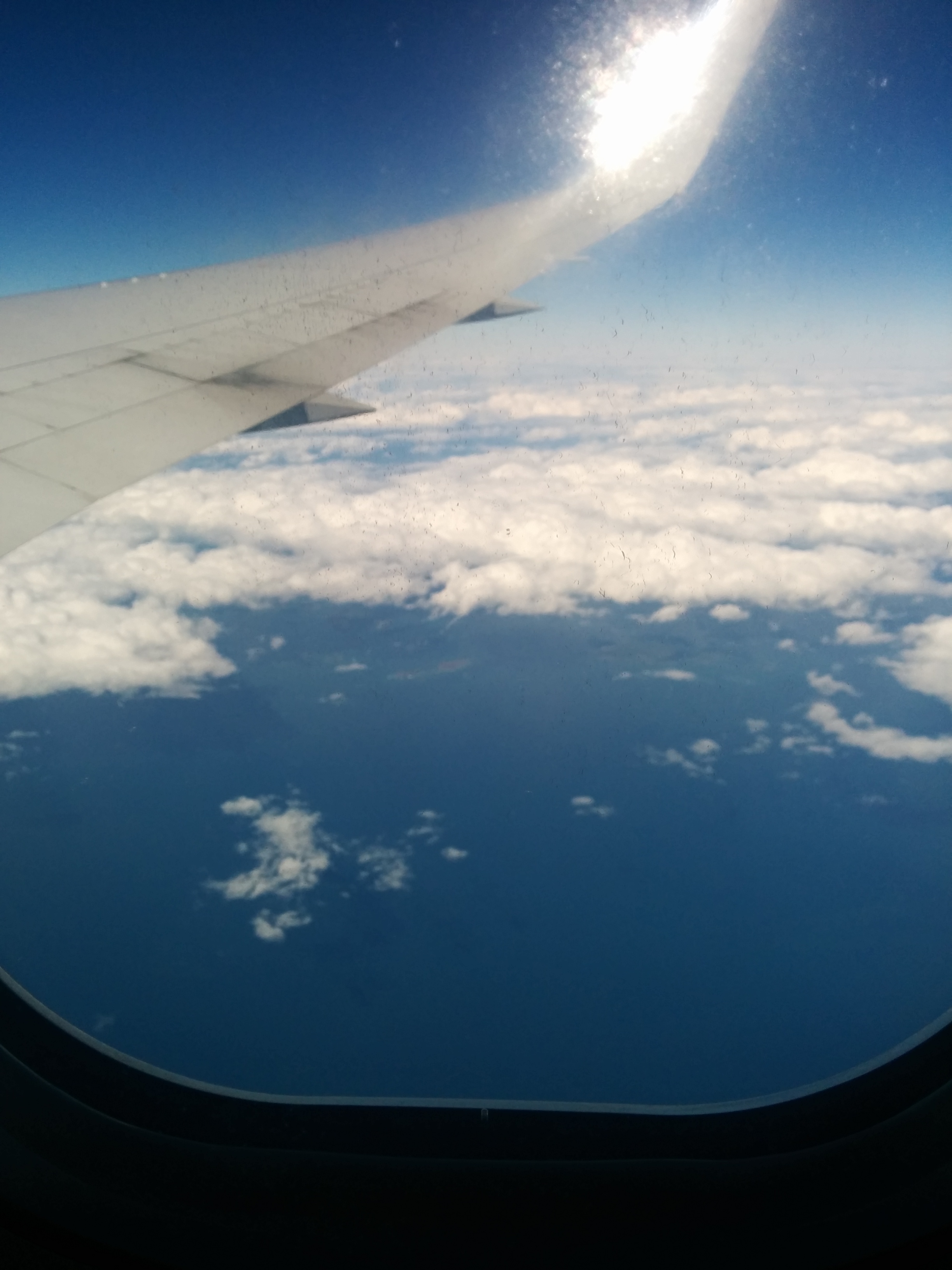
Me (Marco) and Andrea jumped in a plane heading for NY’s JFK airport Thursday morning, with  Bags full of samples, parts and everything necessary.9 hours after we where landing at JFK Terminal 8.
We arrived one day ahead to rest a little and be able to recover from jet lag before the faire weekend.

IMG_20140918_184436

At the customs gate I got asked to explain the nature of the 3D samples I had with me. They where probably worried those had a value and I was going to sell them in the US.
The short lady officer was looking a bit perplexed as I explained that those where 3d-printed or carved out of materials with a machine, and we where attending a faire where the “act of making” is showcased instead of the product, so I wasn’t planning to sell anything.
I had each sample wrapped in bubble wrap, and she asked me to unpack the first.
“This is 3d-printed from a plastic filament” I explained. She stood still.
She wanted to see more. “This is carved out of plywood” I continued.
She did the same with all the samples I had carefully packed, forcing me to unpack.
“You made this?” she asked. “Sort of. the machines we make made those.”

She quickly grasped some of the samples and stared at me.
I tought she was going to kick me out, search me or something, then she jumped off the seat, ran off to her colleagues in the customs and said: “Look, these are made by a machine, how cool is that?”.
I nervously smiled as she pointed at me in the distance with the crowd of traveleres watching the scene in absolute silence. She then came back to her post. “That’s really cool. You can go now!”.

Maker Faire NY was already started. Thanks officer.

IMG_20140919_091516
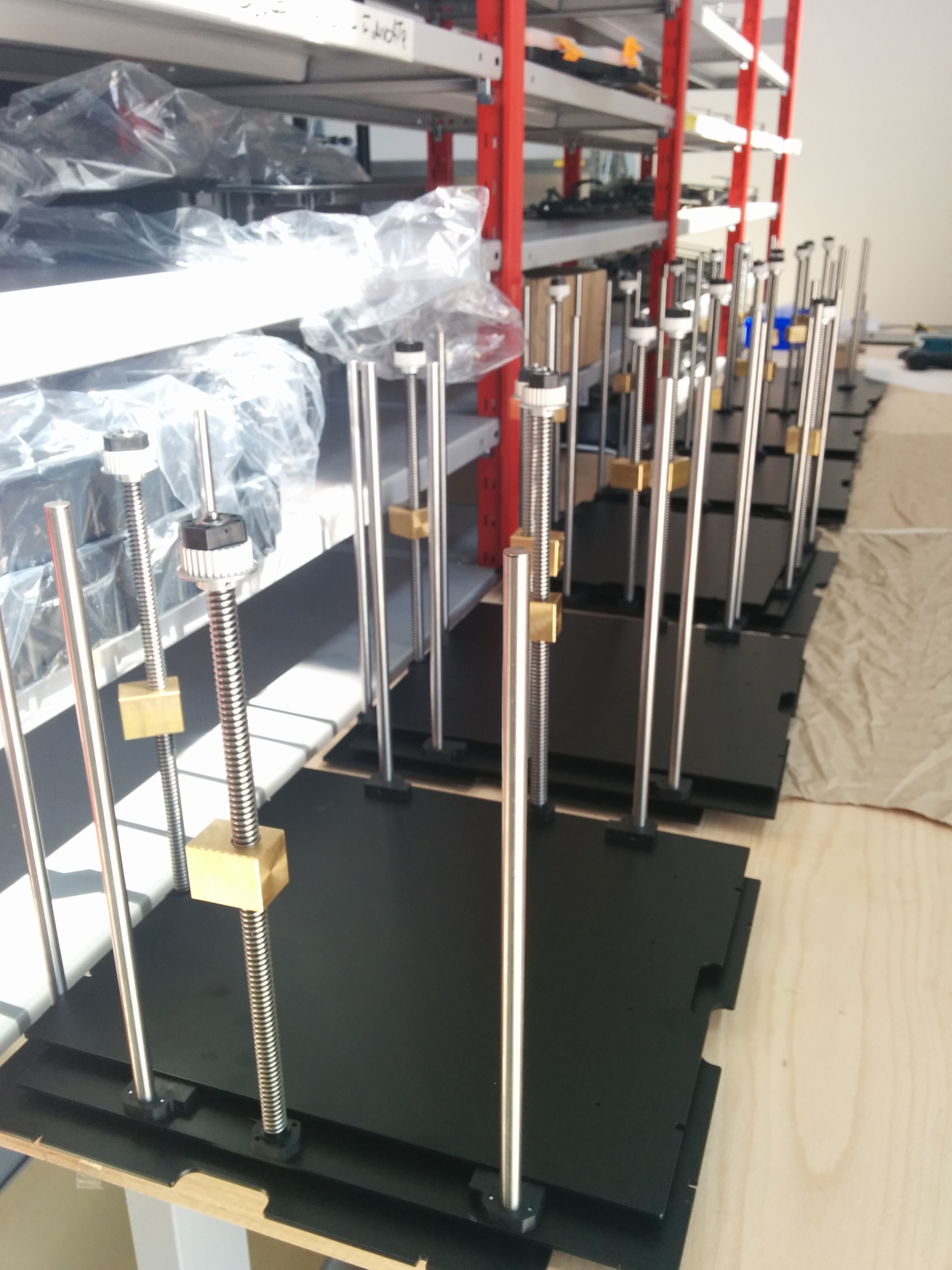
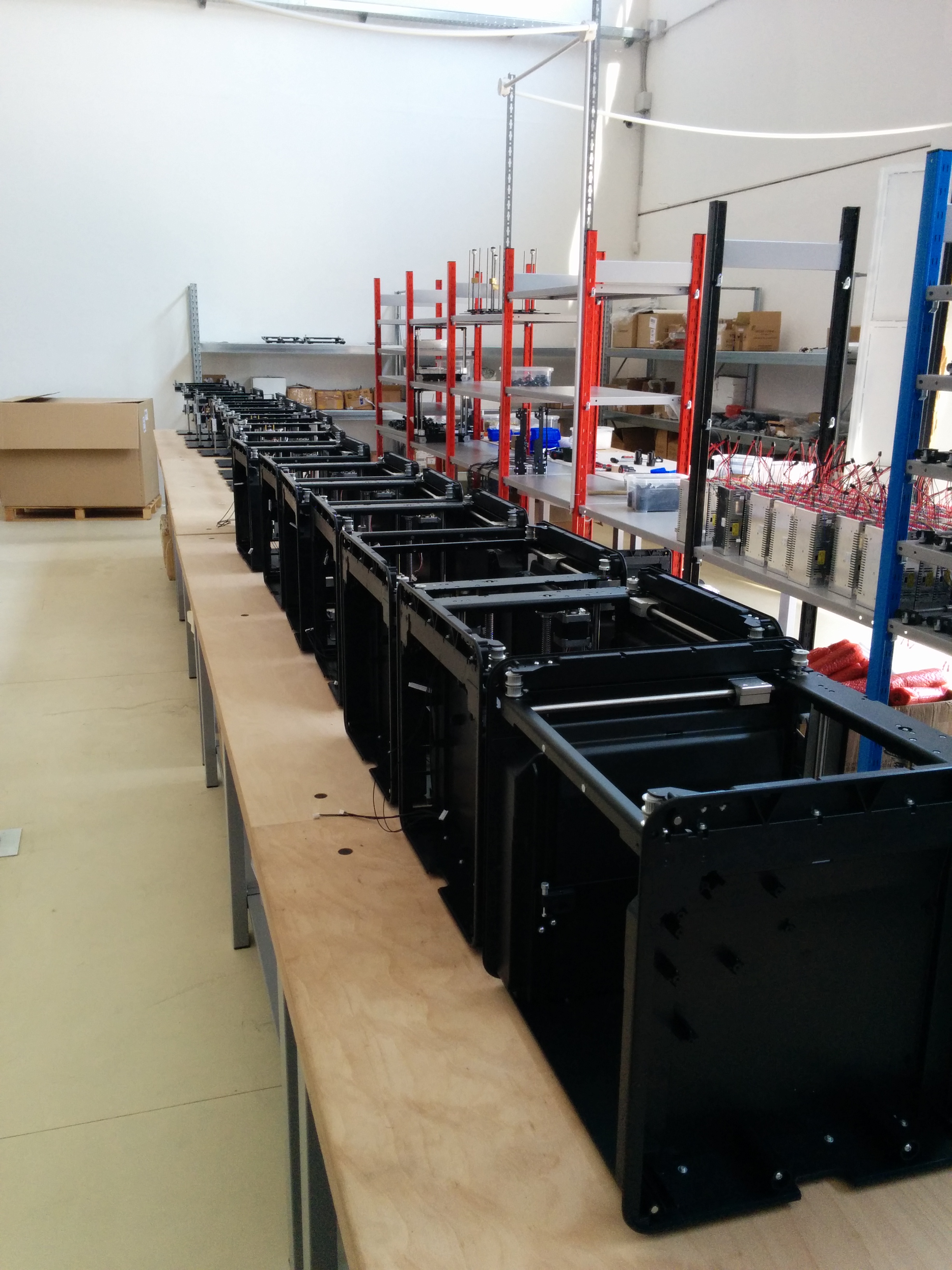
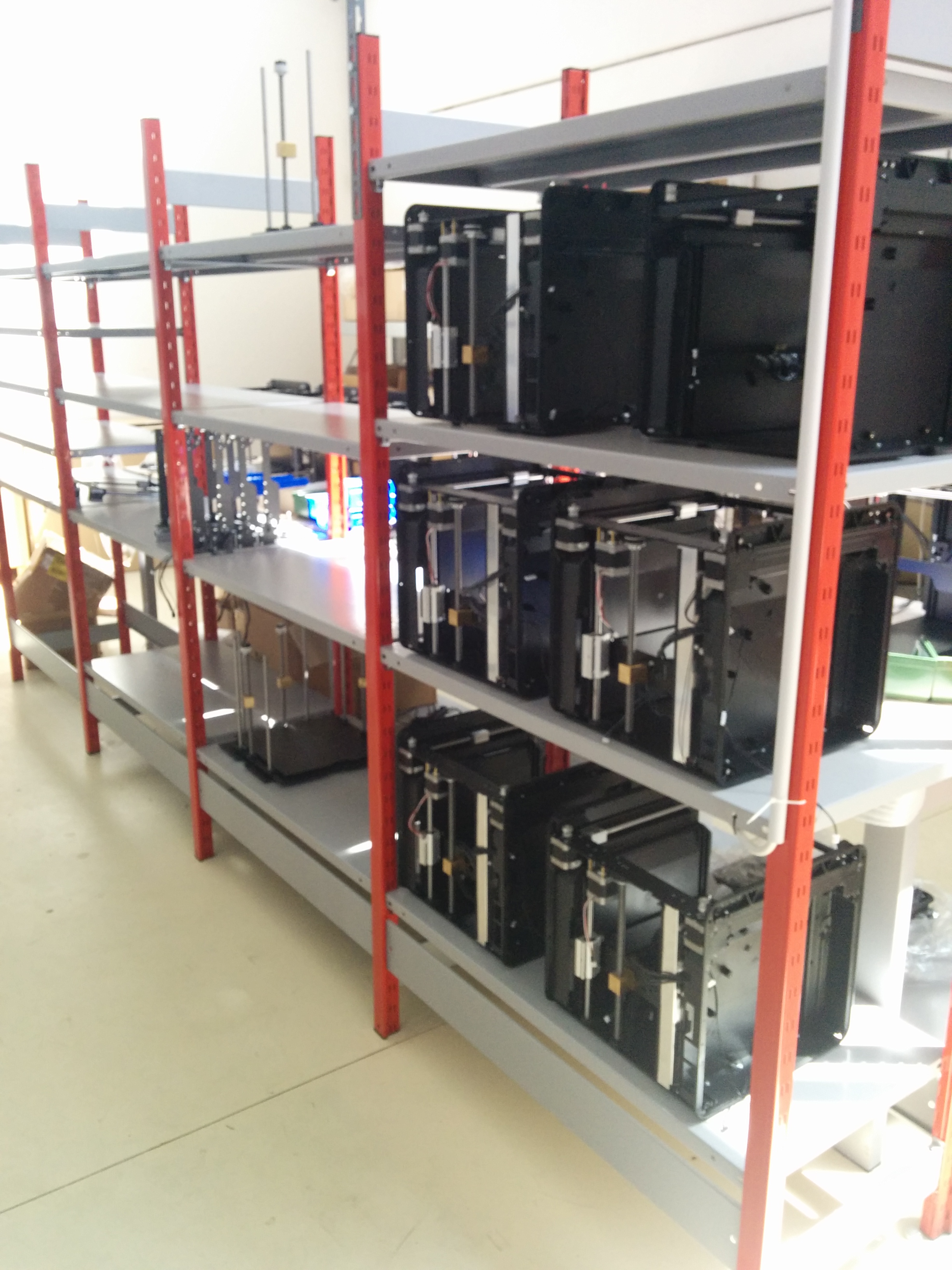
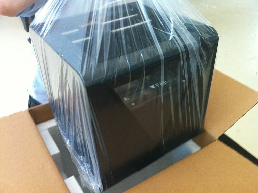
The day before the faire we had our share of hard work, as we had to physically move the 3 FABtotum we took with us from Italy, plus all the booth stuff and computers.
Fortunately we where mostly still running on a +6 timezone and we woke up at 6am so that everything was ready for entrance to the faire by 9:00 am.
Ignoring all the huge booths, we were probably the first ones to receave our exibitor badge! yay!
IMG_20140919_155944

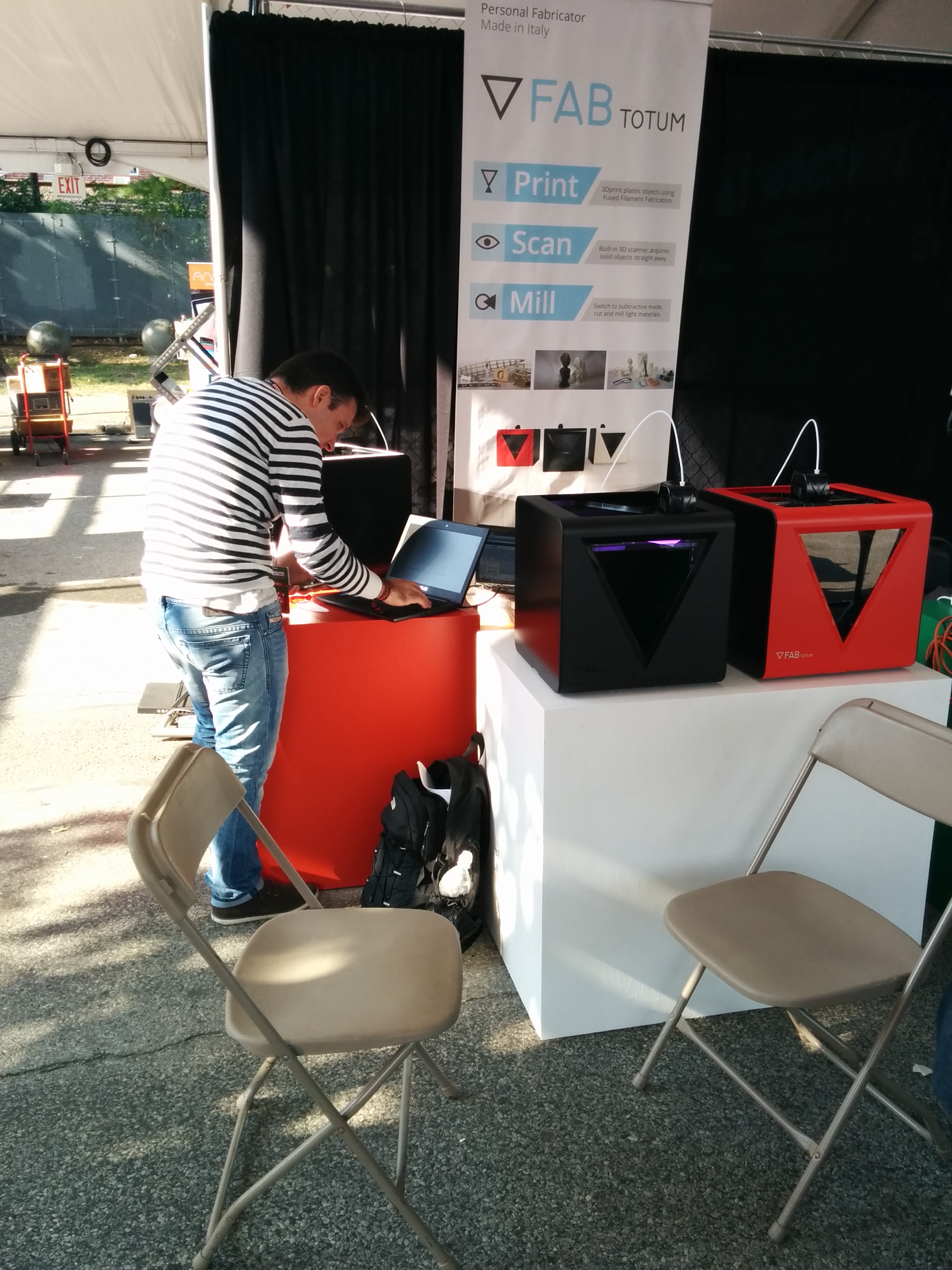
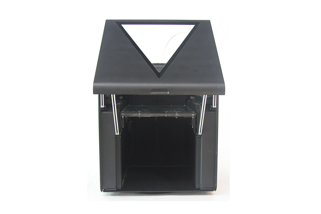
By the end of day one we where settled and started to run tests to recalibrate the machine after the travel. One unit, the white one, received too much love from the express courier and got damaged during shipping. we fixed it back to a usable state, and we used it to scan a coin during the weekend.

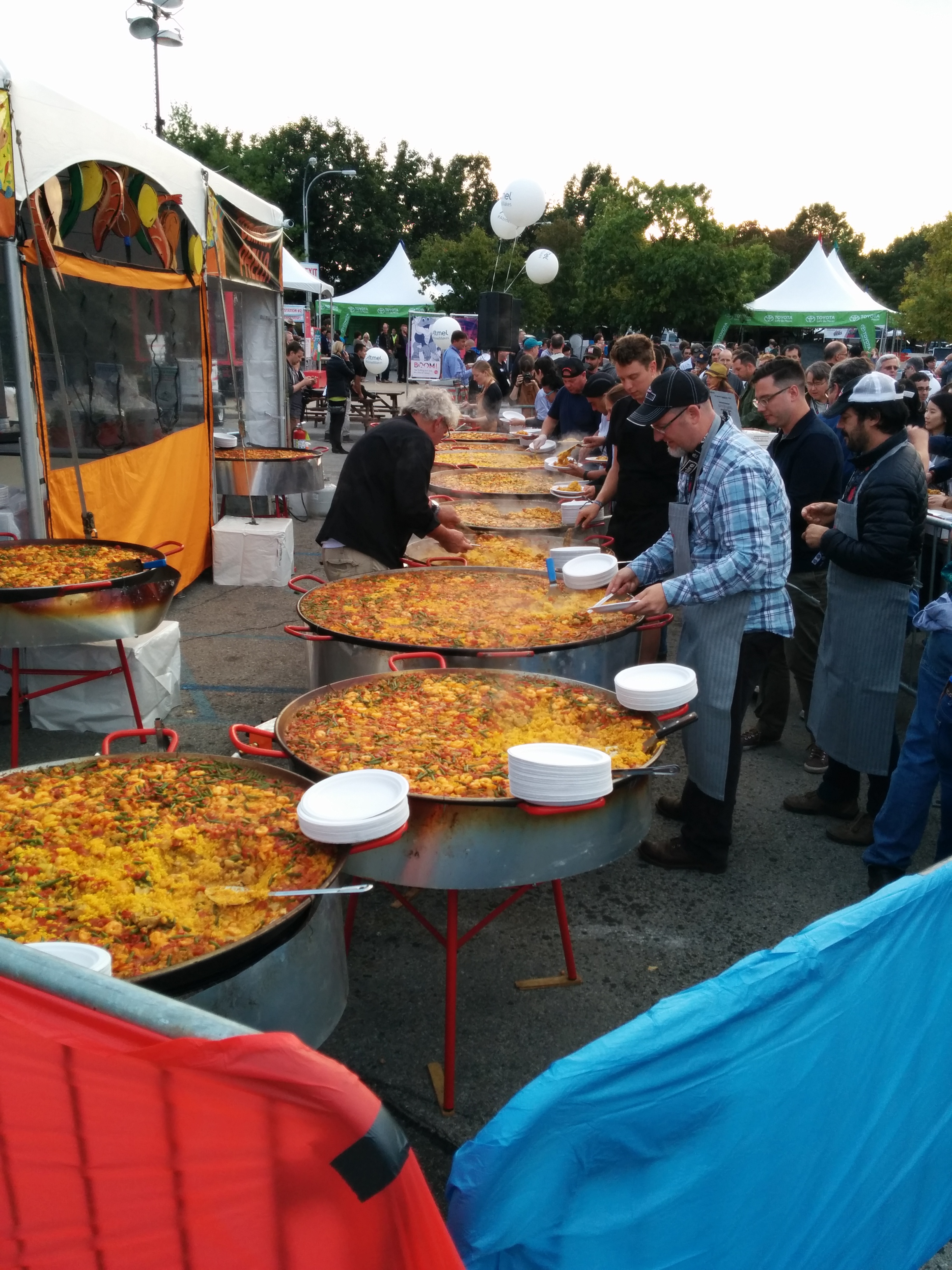
That evening they served Paella for free to all exibitors and workers, it was a nice way to close this busy day. I never seen so much Paella in my life, and it was delicous too.
Add free beer/drinks, nice guys all around , Electro Giraffe providing the soundtrack and the perfect party is served.

IMG_20140919_181137

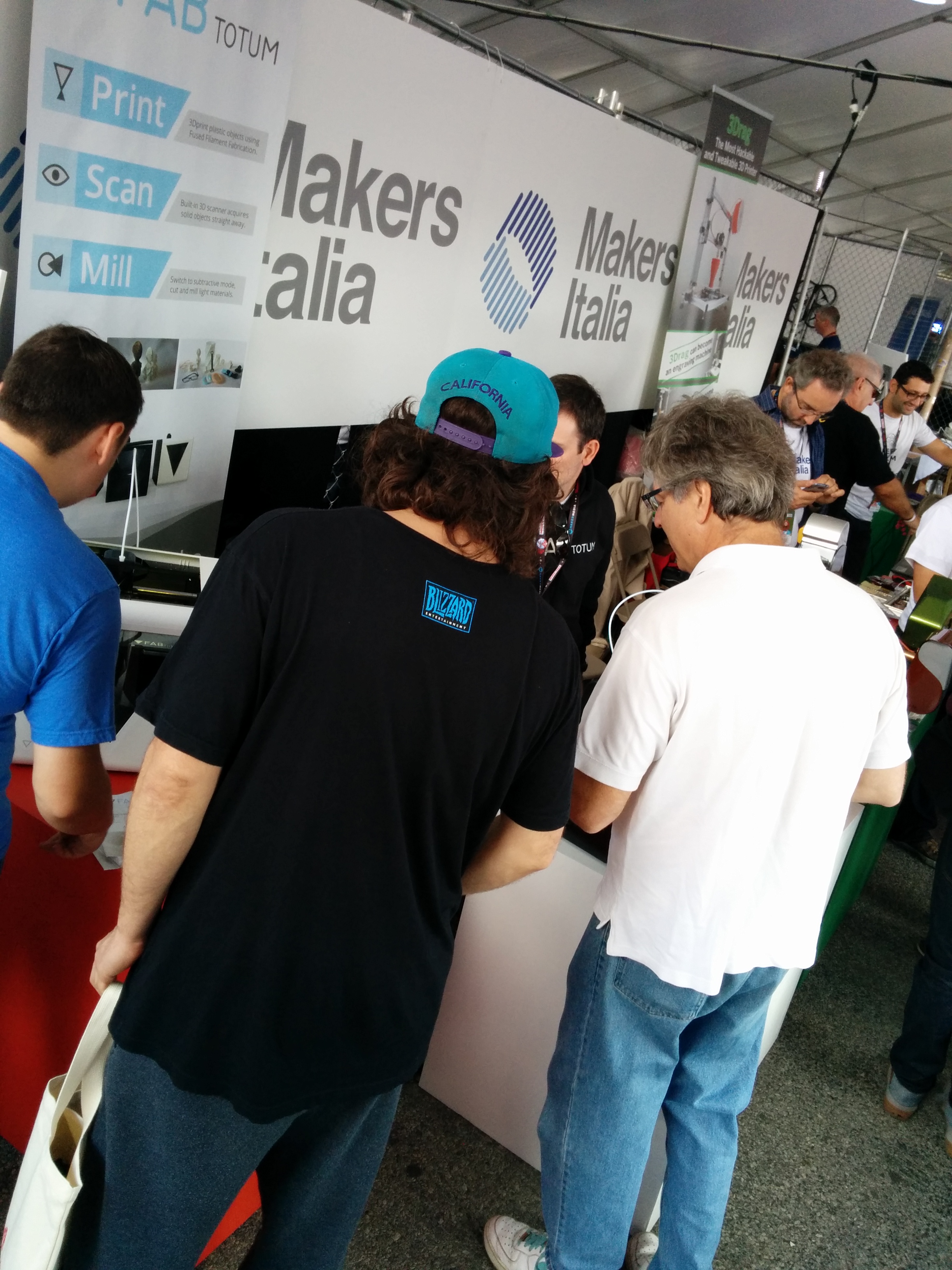
On Saturday, as soon as the faire kicked off, we where flooded with visitors.
We were visited by some Indiegogo backers too! Thanks for coming guys!
Backers where able to touch and interact with the FABtotum, hopefully showing all the work involved and the quality of the build!
Many other exibitors came to see the FABtotum, and despite the small space we answered all the questions, from the simplest “how do you do that” to “how the belt system works”.
Notable visits were from Indiegogo’s Associate Director for tech & Hardware Ben Bateman, Arduino Co-Founder Massimo Banzi (who later made us blush with his tweet), and Maker Media Vice president Sherry Huss.
We where literally stuck for 2 days answering all the questions from the visitors of the faire, so we couldn’t see the faire ourself until the very last hour of Sunday, when we gave each boot 15 seconds time each before closure.

IMG_20140920_120352

IMG_20140921_124008

Finally, on Monday we had some rest before leaving.
We left Queens and  visited Manhattan for the first time, wich was a little bit messy for the UN meeting but cool nonetheless.
In the evening we even had the chance to visit the NYC Resistor hackerspace.
the place is really rad!  Andrea became really euphoric.


What an incredible city, full of contrasts and shades, diversity and communities!
No other place would be more suitable to host  Earth’s “Greatest Show and Tell”.

On Tuesday we left the City. Our country needs us for the European Maker Faire Rome!
But this is just a goodbye, we’ll be back!

Behind the scenes: Production Facility

As the production is kicking off, we shifted the topic of this blog from software & hardware development to industrial/production related topics.
This is going to change soon as we’ll -hopefully- have more time and more details we can share about developing hardware and software on the FABtotum, on ideas we would like to foster and see grow.
In the meantime we  tought it would be cool to show how the assembly procedures outlined in a recent blog entry unfolds in reality.
This ensures all building platforms have the same alignment (flat). Power tools allow fine control over torque on bolts and screws when assemblying.


IMG_ (12)

The Z-Axis Subassemblies ready for installation

IMG_ (14)

Detail of the Z axis Assembly with the Z axis mounted.
Dust gets blown away with a compressor before we ship.

IMG_ (15)

The first mechanical sub-assemblies on the assembly line!  The Personal Fabricator is assembled by joining all the remaining sub-assemblies. It is then moved on another shelf for the final test before packaging.
Early Birds backers: yes, these are units of the Early Birds Batch and Batch 1, these are yours!

IMG_ (13)

More units being prepared for installation of the electronics


Admittedly we’re still moving tables around when needed, because no matter how good you plan your factory floor, you always discover a better way of doing it…by doing it!
In the end all the optimization of the design is paying back now, with low assembly times and reduced possibility of errors that in turns should translate in a better product.

So that’s it for this tech update.
Time for us to get back to assembly, screws won’t screw themselves, right? (?).

In the meanwhile , have you enjoyed the tour? let us know  in the comments!


Interaction design & the FABtotum

One of the most important aspects we focused on, both in the FABUI and in the Development of the Hardware, was human interactions.
The best interfaces -at least for us- are the ones that do not force the user into a specific way of thinking the application but are equally able to teach the user how to use it (both from an Hardware and Software point of view).
This of course was very limited during the Alpha stage, and we basically had everything tied together by intangible rules like “before scanning lets tilt the build platform” and “after you scan, get the resulting files and remember to tilt the build platform”.

The FABtotum is the first attempt on hybrid manufacturing and digital acquisition in a desktop-friendly device. We could not resist: we had to make the software and the hardware interact in new ways.

The result of this endeavour (wich is basically a mix of hardware and software design choices) is something best defined as a mix of industrial design, software interaction design, software user experience.
The result at wich we are aiming can be fairly represented by the User Guide, wich will be digitally available on the website once the FABtotum Personal Fabricator is released.

Introducing new Users to the functionalities (many, admittedly) of the FABtotum was not an easy task.”What is Auto Bed leveling”, “Can I use it during 3D milling?”, “How do I machine a piece of wood?”, “Can I 3d print and Mill at the same time?”. All these are legit questions anyone would ask if not guided and assisted in the process.
The first part of the manual will guide people in the basic knowledge of what you get to do in that  small cube.

Of Course: all of this is consistently portrayed in the FAB UI as well, with a consistent set of icons,with tooltips and quick action menus. But the first thing to teach is to start the FABtotum for the first time and get in.
This section is also part of the welcome kit/getting started inside the cardboard shipping box.

We love concise informations, so the approach we used in most of the manuals and the FAB UI is task-based: to get A you must do 1,2,3, where each number is an operation the user can recognize for it’s use.in other words i’ts much better to not force the user to do a set of (apparently) meaningless and small operations, but to teach him all the smaller (always useful) tasks with a clear focus on the goal.

Getting on the topic of Human interactions, we got to experiment with onboard sensors (endstops,camera,bed sensor) and sensorial feedbacks (lights,RGB ambient lights,sounds).
Third party developers will surely like the way you can interact with the final user, but for starting out we kept everything as minimal and simple as possible.

For example you can auto bed level only if the plane is properly positioned (triggering a function). In a probing operation users will get prompted to a wizard that will actively check for all the requisites in different moments, for example “front door is open”, and “now remove the plane”, until the action is actually performed in real time.

This gives us the potential of guiding and correcting user mistakes without being too much intrusive in his experience: we simply set a wizard with steps for each operation.
You’ll know in wich steps you are and what is happening, and if the hardware is correctly set-up for that.
example: if you choose to Auto Bed level and the plane is not positioned. You’ll be prompted to position the plane…and the FABtotum will be able to tell if the build plane is in additive or subtractive mode, AND if the Gcode you will be printing is a 3d print or a subtractive job. in other words: consistent.
the FABUI and the Hardware is constantly kept consistent to each other, and this is great to build any respectable user experience.

Digital acquisition is the most complex part of the FABtotum and we want to make improvements in this department too. We are still still far from a “click to replicate” approach but we are also miles away from the original concept expressed in the alpha (with scan to poit cloud alone.)
The hardest part is to make people confident with the scanning procedures, wich result expect, what movements and hardware is involved.
This, as before, is done by checking the hardware and guiding the user.

Other aspects covered by the manual as well as the FABUI are cleaning and safety (under maintainance on the FABUI, in this case).
These instructions are also guided as wizards.The “Unload spool” function, for example, is something relatively complex if you look it from the software and hardware point of view, but it’s pretty simple as a single click operation with hardware checks in realtime and user visual feedbacks.

Designing human-machine interactions is a de-facto industrial design topic, but it involves software, firmware, engineering and some patience.

As usual, hit the comment section on the forums to let us know what you think!
FABteam


How it’s made: FABtotum Personal Fabricator

The production and release date of the Personal Fabricator has been pushed back until at least late July to account for late supplies, but that this doesn’t mean production will have to start from scratch.
The FABtotum is no simple object so a good amount of the thinkering done was targeted at the manufacturability of the product.
The FABtotum assembly line is… well, not in line, but a parallel assembly system.
Each sub assembly component has it’s own assembly area, to minimize complexity and promote specialization and productiviy. All the sub-assemblies are gathered together when and where needed to become a completed machine.
We tought it would be extremely intresting to show you how the production process unfolds.
If you are a DIY FABtotum kit backer you might as well get an idea of what are the critical procedures and what goes where. Don’t sweat too much, tough. the most complex sub assembly / components will be preassebled in the DIY kit.
If you are waiting for a fully assembled FABtotum, sit back and watch what has been done under the hood!

head

Head
We uncovered the FABtotum’s hybrid head a couple of weeks ago, so there is plenty of information about it.
the head is composed by a few parts:

  1. The outer shells
  2. The PCB controller
  3. The Extruder assembly
  4. the 200W milling motor

While the outer shell and the controller PCB don’t require assembly or soldering, mounting the milling motor requires the unit to be disassembled and re-assembled with the er-8 motor shaft in place, then bolted to the pcb controller and an Aluminum plate.
But before locking the PCB to the aluminum plate, mounting the cooling fan and turbine, the extruder must be assembled and placed,terminals have to be soldered to the PCB with heatshrink tube in place.
Long story short, assembling the head requires each step to be performed in order, and therefore is probably the most complex part we have.
Considering the importance of the part, it will come assembled even in the DIY version, unless you feel really badass and want it your way.


X Axis Assembly
The hybrid head (as well as any possible head we’ll make) will be carried around the XY plane by the head carriage.
The head carriage is made by 2 identical, interlocking, hi-density polymer plates, with a a couple adjustable belt anchors (two because belt tensioning is needed on both sides of the belt circuit to balance tensions).
Before locking togethere the 2 parts, a couple of linear motion bearings are placed inside along with the lock mechanism and as well as the electronics placed on the carriage.
The carriage is in-fact, a platform on wich the head sits and drains power, but it also feature an LED for illuminating the working area, the laser line generator and the Z-Probe Digitizer.
The Z-probe digitizer is itself made by 3 parts: A servo motor, the probe Arm, the force sensing resistor (FSR). (above the pre-production prototype until we receive the final parts)
Once mounted, the carriage receives two 10mm linear rails, at the end of wich is mounted the X axis support.
The part, mounted like this, is bolted on the linear motion bearings on the Y axis, on the coreXY frame.

CoreXY Frame
While we were talking about the head, and the carriage, someone else was preparing the platform on wich all this tech has to be mounted precisely: the coreXY frame.
This sub-assembly is basically made of:

  1. An aluminum panel, lasercutted and bent to shape
  2. 3 nema17 motors (X,Y,Z Axis)
  3. 4 supports
  4. lots of pulleys
  5. approximately 2,4m of reinforced GT2-3mm belt

The procedure for this, is , despite the premise, a much more simpler task.
The shafts are mounted on the supports with the bearings in, wich are in turn bolted to the frame.
The motors are mounted on the frame as well, and the pulleys are placed in the frame.
The belt (actually 2 parts of it) is then passed on the motor pulley, straight into the X axis support, to the carriage and on the other side of the X-axis gantry as well, following the path exposed in belts and stuff, experiences to share.
ball bearing at the end of both sides of the X axis are used to guide the belt and are locked in place by the same bolt that lock the X axis assembly to the bearings on the Y axis.

In the front a LED board is mounted: this board provides RGB and ambient light inside the FABtotum Personal Fabricator and will be later connected to the “Totumduino” Control board.

Camera
The camera, wich is used for 3D-scanning and other stuff,  can now be mounted on the Y axis, in particular below the left-side linear bearing.
This is a pretty straightforward process involving 3 parts.

  1. A standard issue RPI-Camera Module
  2. A longer Flex cable
  3. Our custom made camera casing/support

The camera is basically taken from the original box,separated from the flex cable, calibrated to focus on a specific distance instead of infinite. This is accomplished by turning the 3.5mm lens casing on top of the module.
We build a custom rig for this, as many other tools that are usefull for bending and cutting parts are made by us for the purpose of assisting the operator in precise operations.
Once calibrated the module receive the new flex cable, wich is longer than the original, and is then locked in place inside the camera casing.
the flex is then bent at specific distances to prepare it for future assembly and the module is bolted to the Y axis of the CoreXY assebly.
the coreXY assembly is now complete.
The RPI camera is well known to suffer from static shocks. Cleaning and static shock countermeasures have to be taken in to consideration, just like elsewere.

Double-face fabrication platform/heated bed
The plane/bed/platform/whatever is maker ingenuity at it’s finest.
It’s made by sticking together a PCB heater with a glass sheet, a suitable polymeric spacer and an aluminum plane.
Ingredients:

  1. Aluminum panel with fixtures
  2. PCB heater
  3. Glass plane
  4. Spacers
  5. locking mechanism (keeps the assembly together)

All these parts comes ready to be mounted and beside some bolts it’s a pretty simple sub-assembly.
A mask can be used to speed up the process as well, but this part is not mounted, it’s provided separately in the box to avoid damaging the part during shipping.
At the end it looks somthing like the picture above, minus the scratches we made by countless tests on cheap spray paint (all the painted parts are processed with powder coating).

A/E block assembly
The A/E block is composed by a miriad of small parts,and it’s the second most complex part in the FABtotum.

  1. Nema 17 motor (E Axis)
  2. 1:20 worm gear reduction
  3. Gearbox casing
  4. Feeder wheel
  5. ball bearings

The gearbox is pretty simple to mount but takes a bit of time due to the small parts and the tuning needed.


Z assembly

The Z assembly is basically the Z plane and build platform support.
To keep it simple, It’s the part that goes up and down, and It’s composed by the following parts:

  1. A/E block (subassembly)
  2. Linear bearings
  3. Aluminum brakets and mounting plate
  4. rails/shaft supports

While not part of the Z axis, the lower bottom panel is used to mount the shafts and as a mask to calibrate the Z axis during the assembly.
Once mounted the part is ready to be used as a base for completing the assembly process.
Oh and I almost forgot: silicone rubber feets are sticked under the botton panel with a mask.


Electronics
In the fabtotum the wiring and the electronics are already pre-made so the assembly process is simply connecting things and bolting the PCBs in place.
This part of the assembly is mostly carried out in the left-side of the machine, inside the 45mm deep pocket of the structural side panels, but some wiring stretches out to get to far components like the carriage (served by a flex cable) , the Led board  in the CoreXY assembly and safety switches on the far side of the device.
The first thing is mounting the 24V power supply unit inside the side panel.
then we have the Totumduino board, wich is bolted in place on pillars, with an heatsink attached on the far side for heat dissipation.
On top of the board a cooling fan is mounted over the five (yes five) Allegro A4988 stepper drivers for the X,Y,Z,A/E,B axis.
All the motors and connectors are plugged in place.
the Raspberry PI is then bolted in place with his main pin header mating with the Totumduino.
Ok that sounded dirty.

There are around 6 switches that are used either for safety purposes (AKA checking the machine is not milling with the front panel open), endstops, homing switches.
At this point the side panel, containing the brain of the machine, has some connectors sticking out, ready to be united with the rest of his body.


Chassis & cover
The next step is the final assembly step.It involves connecting all the parts and using the outer shell to complete the task, as it serves strucutral purposes as well as aesthetic and safety purposes (to enclose the building area and cover all the mess behind).

The chassis is composed by:

  1. Front facing cover (the “main panel”)
  2. Top covers
  3. Rear cover
  4. Side panel
  5. Side panel covers

The Z axis assembly is joined to the CoreXY assembly.
The Z axis Motor is connected to the Z axis leadscrew with a closed loop belt.
the CoreXY, standing on the top, is bolted down and the mechanical core of the FABtotum is completed.
The Side Panel containing the Raspberry Pi and Totumduino Board, as well as the PSU and part of the main wiring infrastructure of the FABtotum is bolted in it’s place by using holes pre-drilled on the CoreXY frame and the Bottom panel frame.
the same is done to the other side panel, wich normally contains the filament spool within is width.
At this point all the wiring is finalized by placing snap-in adhesive clips and by conforming the wire to the narrow passages. Endstops are bolted in place and the Ledboard is connected.

the side panels are closed by adding magnetic locks, the top and back cover is locked and bolted in place (the holes are placed on the side panel, therefore this operation was possible only now and after the Z carriage is finalized!)

The last part is mounting the front cover, with his brackets and arms.
the front cover is therefore comparable to a sub-assembly itselft, with the front windows and side brackets to be mounted separately.

IMG_2588

Software Testing, Quality Assurance

Before closing the side panel covers (wich can be opened and closed thanks to a magnetic lock) a pre-cooked 8GB SD card is inserted in the Raspberry Pi.
The card contains the OS and the Software (the FABUI) necessary to run the FABtotum.

A self test procedure involving movement and functionality  is run to verify that the machine is worty :

  1. Extruder turn on, reach temp, turns off
  2. Bed turns On, reach temp, turns off
  3. Milling motor turns on, off, RPM stress test.
  4. XYZ speed test procedure.
  5. Carriage assembly control:
    – Probe extension and retraction
    – Light on/off
    – Laser on/off
  6. Test print of a sample file.
  7. the carriage and the Z axis are moved to a safe shipping position.

At the end the software is reset and the machine is back to factory settings ready to be packed.
Other QA procedures involve checking for the presence of defects or scratches that could occur despite precautions.

3cawcoSqZifXCs8DulCk13QCLjvAe-WrG51akkXteEw

Packaging

The machine is then moved from the test bench to the packaging area.
A Moisture-Absorbing bag is placed inside the FABtotum to guard humidity during shipping.
This is pretty important since we will be start packing the FABtotum during summer, where in Milan we have usually 70-85% relative humidity at around 30°C. Yeah it’s a torture even with air conditioning.
While stored in the courier airplane cargo bay. the temperature of the air will go below dew point, causing the water content of the air to condensate, trapped inside the plastic bag. The moisure absorber is there to avoid that.
The Build platform is wrapped in bubblewrap and placed inside the FABtotum As well.
The welcome kit (including instructions and other documentation), the wifi USB dongle, the Hybrid head , the Ethernet cable, the AC cable are all wrapped in bubblewrap and stored inside the FAbtotum.
The axis are blocked in place and the machine is put in a PET transparent bag.
The shipping box is prepared and 4cm-thick estruded polystyrene shells are placed on all 6 sides, giving maximum protection.
Once the machine is placed inside, the box is closed and sealed.

Shipping

Of course each machine must get to a separate destination, and one FABtotum can be red,white or black.
A computer connected to our database assist in the final shipping procedure by creating a shipping invoice /documentation and preparing the pickup with the Express courrier.
Once the box has left our facility ur system will forward the tracking number to the provided email address.
And there you have it!
this is how a FABtotum is made.
As you can see it’s a lot of work to produce one unit, and the amount of parts,components and procedures involved is huge.
But by streamlining the assembly and simplyfying some procedures by breaking them down to sub-assemblies the production of the FABtotum personal Fabricator is a straightforward process.


As usual we are well open to suggestions and reading your feedback.
head over to the forums to leave a comment.


, ,

FAB UI, the FABtotum user interface.

A while ago we talked about the FABtotum User Interface. Today we’re back on the topic to discuss some of the features of the FAB UI.
You may have seen many 3d printers web interfaces, but how many multipurpose personal fabrication user interfaces? None? so did we before starting this project.

In the Alpha version of the personal fabricator there was simply no user interface. to print you had to rely on external software like Pronterface to print, a processing script to scan on the PC.
The main challenge we faced with defining the FAB UI was to answer the following questions:

  • How do you provide a integrated panel to assist you seamlessly during all the personal fabrication process?
  • How do you do that without making the interface too complex or alienating the user?

FAB UISetup Wizard
Once the FABtotum starts for the first time, the user is asked to set it up selecting a wifi network, user & password, and other things.
The informations provided (like email, user etc) are saved locally on the FABtotum SD card and are used to identify the owner.The email in particular will come handy in future updates.

User Login
A log in is required for safety and security purposes.
Safety because someone in your network could just access, push a botton and crush your hand while you are adjusting an object to scan in another room, Security because your local file database, as well as your informations or projects should not be shared unless you want to.
This makes also perfect sense if you think about connecting the FABtotum to the internet and allowing remote logins.

The Dashboard
The Dashboard is the first page you see after loggin in.
Current tasks and previous ones are saved here. The dashboard can be costumized by changing the position of the tables. Plugins (see below) can alter or add elements to the dashboard as well. Right now we are sticking to the “less is more” principle, but you might as well fill the page with everything you have or you develop later.

Scan
The scan menu is actually a section of the UI where you can select more than one scanning method. you can find some insights of those methods here.
As you can see each process is guided in a wizard-like procedure, wich has been chosen because it can break up the informations needed in multiple tabs, without flooding the screen with informations.

for example the scan quality (wich is determined by the camera resolution, numbero of points collected and postprocesses used) as well as the scanned area, can be selected with draggable controls.

A rubber duck is used to show the differences between the various settings.

Create / Print
The create menu is directly connected with the object manager (see below) to be able to print or mill directly from the available objects you saved.
You basically select the compatible files and click next.
Before printing you are prompted with some info (depending on the situation) and tips on how to better print or mill.
During the print process the user can override speed and temperature, while keeping an eye on the process.

Once the process is started some functions will be locked (for example you won’t be able to jog or make scans, but you’ll be able to browse the library.)
Thanks to this approach you may as well launch the print from your desktop PC and then log in the UI with a tablet and follow the print up close, like we did during the tests of the beta prototype. This is also true for remote access (connected to the UI over Internet).

Jog
The jog feature is a must have in each and every CNC machine, to position the machine and do manual operations. The Jog in the FABtotum supports both additive and subtractive machining, allowing to switch from additive to subtractive (A/E). The Jog interface can be costumized easily.

Object Manager (aka Object library)
This is where things gets interesting.
You can “upload” from the client (your browser) or from a USB stick the supported files.
In the FAB UI one “object” is not “one object”. Let me explain:
You scan an object using the rotating laser scanner. you get a point cloud file. but the thing has holes because of the limits of that particular scanning method.
You go back and do another scan with, say, the Z-probe.
You now have 2 clouds. If the points are enought to reconstruct the object you can go ahead, otherwise you can reiterate this process.
Once you are done you’ll have, let’s say, 3 ASC cloud files.
From the Object manager you can join those parts and obtain the complete point cloud.
Once you have that you may download it from your browser, or try to reconstruct it onboard (experimental/WIP feature). either way you obtain an STL.
Now you have 1 cloud file and one STL.

You can slice it directly on the FABtotum (experimental/WIP feature)  and obtain a G-CODE.
Let’s suppose that your object is made of more parts, and some of them are not made with 3d printing, but with the built-in milling motor of the standard-issue hybrid head.
You can add another GCODE to the “object”.
Or you may add another STL to slice and obtain all the parts needed.
Or you might want to run the mesh recontruction on a good PC to increase the quality of the scanned data. Guess what? you still have the raw point cloud to download and process!
The result, as you can see, is that the user doesn’t need to mentally switch from additive to subtractive or “plan” too much, and will be prompted by the interface to perform manual operations before starting different procedures if needed.

Plugins
Since the FABtotum can be used for many purposes other than the ones natively supported, one of the objectives of the development of this interface was to allow costumization where it made sense.
Plugins can be developed as an easy way to add functionalities to the interface and the device without introducing changes on the interface structure.
This way each plugin can be shared across all FABtotum users easily.
One plugin, for example, would allow STL or Gcode previews during the “create” process, something that required some external software.
We demoed this concept with the excellent Gcodeviewer by Joshua Parker.

We expect to see many great plugins from the community and we are planning to host those and allow direct download and installation directly from the interface (CMS-style).

Settings
In the settings page you can decide how the the FABtotum and the interface behaves.
Some of the settings are about the the device, others are about the appeareance of the UI.
one example is chainging the skin/theme of the UI, the other is setting the lights inside the working volume, directly changing the RGB values.
In the settings we plan to add diagnostic tools (like a “self test”), or a cleaning wizard, a leveling wizard, or a spool change procedure, etc (not showed here).

We also have python running in the shadows, provinding that middle level of interaction between the UI and the Firmware (see development update 4 on IGG).
This is used for example, to give the user access to a python script running at boot, wich runs with root privileges and can be used for a lot of things. Really lots. of . things.

Updater
On the FABtotum UI you can always check the latest updates available from the FAbtotum server. The update process is guided and automated both for the UI and the Firmware itself.
Those updates (I won’t stop to underline this) are not mandatory, they are just suggested by the UI since we plan to improve the interface further and eventually fix whats breaks in the process.
The updater notifies the user in the top left corner (the blue zero means no update has been found due to lack of internet connectivity).

Open source development:
Speaking of updates, the software sources will be online on GitHub under the Creative Commons Attribution-Noncommercial-Sharealike 3.0 Unported Licence, when ready. contributions will be integrated in the stable version and released for everyone.
Same goes for the firmware!

Belts and stuff: experiences to share.

We are finally back with an insanely long Blog Update!

With the FABtotum Personal Fabricator we went through a series of experiences in designing a proper belt system, and we thought it might be cool to share this experience.
Some designs spawned several prototypes, some of those where a step forward, other a failure, but all helped us progress to today’s development stage.
Here a bit of the story.

When dealing with hybrid machining you face a serious limit: provide fast movements and high accelerations (especially the latter) for additive fabrication and, at the same time, be able to have a very high inertia or pure “strenght” during cutting and milling operations.
For compact sized hybrid devices the answer has been in introducing new belt designs to keep forces under control and provide fast movements if necessary.

The first attempt can be seen in the Alpha prototype.
The Alpha Belt system was a modified carthesian one.
This version was the starting point in trying to mix subtractive and additive fabrication with a belt design.
In this version the Y axis motor drives a long belt that goes around the building space.
The X axis motor moves the head carriage with a normal belt. The best thing about this design was inertia and stability, but acceleration and noise was pretty high, due to a custom double-sided T5 belt.
The belt tensioning had to be perfect and the circuit was split in 2, so you had to manually balance the tension and try it a couple of times before getting it right.
It wasn’t the fastest and the strongest belt driven system but it could get the job done.

The system itself can be simplified as follows:

With respect to a simple cartesian motion in which each motor has his own belt and axis, the above design is more balanced, so that any force on the gantry is supported by an opposing force each time, easpecially when moving and cutting near the borders of the working plane.
From a mathematical point of view, however, the forces can be calculated easily as any cartesian system (0.5 Nm Nema17 motors have been used to fill the variables)


Eventually, we moved to evaluate a variant, in wich the Y belt was connected to the other side of the Y bridge.
This was a intresting concept that, however, had a flaw: space consumption!
The Y axis (moved by the blue belt) runs around the structure,
The next major attempt in improving hybrid manufacturing was during early alpha, with the HBOT design.

The Hbot design, like the CoreXY (of wich we’ll talk in the next paragraph) uses 2 motors connected to a single belt.

The system works like a ship pulley (or “block”) where the force is split in half. In fact it works like a 2:1 reduction.
You don’t need to lift the W weight, but only half of that, because your movement is reduced by a factor of 2.

In an H-bot or CoreXY system the X or Y movements are basically a sum of 45 degrees vectors. We are effectively working on a tilted reference cartesian chart here.
Since vectors add to one another the resulting force in the normal XY plane is much higher. Sounds complex? here a scheme:


As you can see, with the same motors you get a different result than the basic cartesian system, with twice as much force in each direction (except in diagonal moves, ergo in the direction of the native tilted reference cartesian system). The price to pay is the distance you move, wich is effectively reduced to half, just as expected.

This alternative driving method was simple and effective in most movements and condition but one: X-axis movements. To fight the movement on the Carriage, forces have to be balanced properly. If the XY carriage faces resistance (like in any machining), there is a resulting force in the gantry that causes the gantry itself to flex, generating positioning errors.
This is pretty clear if you think of “what is holding what” and looking at the gantry.
The Hbot design can bring substantial advantages during additive manufacturing but it’s not suitable for subtractive machining due to this problem.

To balance the forces in a belt driven design, systems like the MIT’s Core XY have been developed, and we did some research too to see if it could fit our application.


From a movement point of view the COREXY can be summed up as a normal cartesian motion tilted on a 45 degrees angle, just like the simpler H-Bot (see http://corexy.com/theory.html).

Unlike the H-bot, however, the CoreXY introduced a crossed belt that balances the forces on the gantry. From this basic implementation the COREXY is a valid hybrid system that however has some flaws.
First and foremost, the belt is very long, introducing a “dampening effect” due to the belt extending under tension.

One solution is the one to increase the belt size, but this means more friction, noise and loss in force in a system with 8 idlers and 2 motor pulleys for a total of 8 90°angle turns and 2 180° angle turns.

Never cross the belts
Try to imagine all life as you know it stopping instantaneously and every molecule in your body exploding at the speed of light. Ok it’s not going to happen but that’s what you’d deserve for driving belts that way.
Belts in the coreXY are not running on the same plane because they have to cross on one side to balance forces. The result is that each tooth of the belt entering the pulley encounters a non-straight pulley, wich results in noise and possibly ruining the belt in the long term. We love the coreXY beacause it’s essentially a great and smart solution. Many things like belts crossing could still be improved in the FABtotum and so we started working on it tirelessly to squeeze each and every last Newton we could.

But before continuing let’s have a recap of some of the belt-driven systems we considered during the Alpha and Beta development.
Our interpretation of the Core XY solution was to avoid crossing the belts, like in a H-bot style design, but still having the advantage of balanced forces of the Core XY design.
The solution we adopted was to have 2 closed belt loops, on two different planes.


This way effectively compensates the Hbot torque on the gantry with the help of the belt on the other side. At the same time avoids unortodox pulley mis-usages.
The system works like this:

M1, the left motor, drives the red circuit, while M2 drives the blue circuit.

Those 2 belt circuits run each one on different levels, always straight and do not cross.
Two equal and opposite forces “F” separated by a L distance generate a torque of M=2FL.
In this solution the forces generate a couple on the carriage, wich is effectively mitigated by the short distance between the 2 forces.
If we compare this to the Hbot, we basically moved the problem in a location where it couldn’t affect the system anymore.
In other words, while in the Hbot “L” was really big (the distance between the motors) now L is the distance between the 2 anchor points on the carriage/head wich can be as small as we want. 2F*(small L) = Small torque.


Of course this is just a part in the bigger game that is “making the thing faster,better,stronger”. Part of the improved machining capabilities can be traced in improved stepper power management, but also in a lighter carriage and moving parts.
Le’ts see more of that, shall we?

Structural superiority, part II

With the belt design out of the way, the mechanical team lead by FABtotum’ Chief Engineer Alfredo Marinucci started working on the improved structure for the Beta Version.
When we started the Indiegogo campaign we developed the simpler and most effective way of keeping things together, but thanks to the campaign’ success we could afford to be more bold, and to push the structure even further.

The pursuit of a good-looking, solid, simple and reliable structure is the main problem of any design endeavour, and this was also true with the FABtotum’ structural outer shell.
Italian Design is well known to have never turned down this challenge before, from the field of engineering to pure aesthetics choices.
With the design process of the outer shell we went from a flat design that was a mere accessory made in a single material, to a complex and reliable part.
The shell is made with a composite material: an fiber-enriched polymer, that is capable of withstanding more load than the previous one.


We didn’t have any prototype of the outer shell until last week, when we finalized the molds (see last IGG update). From then we were able to start building the pre-production prototype with the outer shell, covers, bells and whistles, instead of the “naked” prototype we showed recently. The company we are working with to produce these parts has a long history in automotive industry. The fact is that the new shells are in no way cheaper or weaker than the Alpha side panels, but they add a new level of reliability and quality to the FABtotum.
With Alfredo’s passion for automotive engineering and the materials used, you could as well compare the FABtotum’s structural shell to the 3d-printing industry equivalent supercar racing chassis.

Hybrid manufacturing
One of the most important parts of the hybrid manufacturing design is how you actually mill/cut in the end.
The FABtotum uses a 200W brushless motor with a custom made (and soon to be open source) ESC to pilot it. This setup has been proven solid and a definitive improvement over any other Beta prototype we tested, including AC spindles.

The chuck and the axle of the motor are machined for precision, but we have different suppliers with different specs to look into it as one of the last assignement in the development of the FABtotum Personal Fabricator.
Those are the last things we are deciding this month before ordering parts.

Overall, hybrid fabrication on the FABtotum is possible thanks to several solutions adopted.
From the alpha we where able to change many times our approach and end up with something unconventional but reliable.

As with the mechanics many things contribute to the effectiveness of this sub-assembly, like bearings, power control and cooling.

Closing words

This is it for today’s Dev Blog entry,
Hopefully we showed some light on the mechanical development process and how important it was to us, how much effort we put into it and why we think we did a good job.
We know there are loads of things you would like to know, and things are getting ready pretty fast. We ourself can’t keep track of the advancements.
Proof of that is this very post that has been postponed because it became obsolete in one week!


It has been a long way from that prototype (wich admittedly has been savaged for spare parts from time to time). While the time passed very fast, we can’t really make up our mind on the sheer number of things we investigated and tried before committing to a change.
With Indiegogo’s upcoming campaign update we plan to show the final pre-production prototype as we prepare to start manufacturing during April.

hold on until then!


related links
https://github.com/ErikZalm/Marlin/issues/463
http://www.edn.com/electronics-blogs/mechatronics-in-design/4368079/So-you-want-to-build-an-H-bot-
http://www.anthonyvh.com/2013/05/21/halubot-part-1/
http://www.cnczone.com/forums/diy_cnc_router_table_machines/51485-make_gantry_rock_solid.html
https://groups.google.com/forum/#!topic/h-bot-and-corexy-3d-printers/1gb6oo291zI


FABtotum Electronics in the wild.

fabtotum_board1
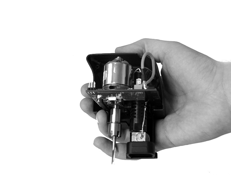
As all computer-controlled devices, the FABtotum rely on electronics to perform all the operations needed, both from a computational and physical point of view (calculate what to do and correctly move motors accordingly).
In a CNC device, movement and I/O controls are an important part of the electronics design.

During the alpha development we used a RAMPS (an arduino Shield) mounted on an Arduino mega,a common setup for DIY 3d printers.
Like us, many people in the community enjoyed this kind of simple and convenient setup, where the instructions (in the form of GCODE language) are executed and the I/O managed from a single unit.

When we started the Indiegogo campaign we had no real need of changing that, but thanks to the feedback of the backers we set a goal to improve and push the envelope for this compartment in the FABtotum Personal Fabricator.
As you know the brain of the FABtotum is a Raspberry Pi Mod B, a hugely supported ARM-based single-board computer.
The raspi added a bunch of neat possibilities to further develop the FABtotum platform with the capability to run complex programs.

To move the motors, sense the environment and control heating, extrusion and machining you need what’s called a power control board.
We have one, connected to the Raspberry Pi via GPIO pins.
So, lets see the (yet unnamed) Arduino(TM) derivate board!

The board itself is not that bigger than the Rapberry itself, sporting a 92x85mm rectangular shape.
A good amount of time has been invested into optimize this, thanks to a 4-layer PCB design. This choice is not just for saving space,but to enhance power distribution on the board.

Power supply is a key element in controlling CNC applications and robotics, and there is a lot going on in terms of power management here.
First and foremost, the board is powered by a 24 volt power supply instead of the usual 12v.
This means less currents , less ohmic dispersions, thinner cables, faster stepper motors, more power to hotplate and heater. The board can supply the raspberry with the needed power from his own power supply, along with a integrated Raspberry Pi logic level interface circuit (+5V <-> +3.3V).

More power does not mean less safety: the board has been designed with advanced solutions to minimize potential damages to the unit and maximize his life under hard working conditions.

All power Outputs provide positive voltage instead of negative, for safety purpose , meaning that if an output is off, there is no voltage at all.
In the RAMPS design even if the negative output is off, the positive pole of a connector was still on, meaning bad things could happen.
More than that, power outputs are designed with inductive load protection, to avoid voltage spikes during turn offs that could damage the drivers.
On top of all this, we have an integrated sinked current acquisition and control
circuit that allows to check and manage power consumption of the board and the stepper
drivers, meaning that also motor tuning can be done digitally.

The board is, of course, a 5 (yes, FIVE) axis control board, with highly enhanced heat dissipation design on each of the five stepper drivers.

On the board we added many other utilities like buzzer for audio feedbacks as well as various RGB lights to make human interactions easier with the FABtotum Personal Fabricator.

From a developer standpoint, the onboard ATmega 1280 can be reprogrammed directly by the Raspberry Pi and the FABtotum web interface. This means that we’ll ship the electronics with a modified Marlin Firmware, and you’ll be able to update the FABtotum or edit the source file, compile and flash it from the web UI again without connecting anything or pushing reset bottons inside the case, neat uh?

If you are really into electronics and you cannot resist puttings your hands on it, we placed an informative silkscreen on top of the black layer. Some fiducial markers are there  for automatic population of the board, meaning that the board is ready for automated assembly with pick and place machines.

So, Looking at the board, you can recognize the following I/Os:

  • 16 poles – 4 axis connector
  • 5th axis on a 4pole JST connector PH series 2mm connector
  • Endstop n1
  • Raspi GPIO header connector
  • Hotbed connection
  • emergency switch
  • Case-door safety switch
  • Front door safety switch
  • YZ Endstops
  • 24 v Power supply
  • interior light output
  • Second Extruder temp
  • Head connector (this includes: Milling motor control, Extruder 1 heat control, Servo control, Servo powering, Laser control & power, Head light power, probe input,fan control and an I2C bus, X endstops, led controls.
  • Board Fan power

We hope you liked this update, hit the comment section in the forum and let us know what you think!

Scanning: (R)ock (P)aper (S)cissors

With the last dev blog update (from November, ugh!) we have showed some RasPiCam calibration in order to have better image quality during scans.
You also have seen a very early glimpse on the FABtotum UI, so you can have an idea of how both hardware and software coexist.
Today I want to talk a little more about how we are accomplishing the 3d-scanning functionality of the FABtotum Personal Fabricator, in a more specific way: how the different types of physical-to-digital acquisition works.

Rock Paper Scissors
Like any tool, there are certain situations where one tool is better than onother one, even if slightly different, but no tool is always better. That’s the case with the 3 main methods of digital acquisition the FABtotum personal fabricator is capable of.
Such difference is clearly visible in the software environment we are developing, where those 3 different functions have each one a different set of instructions and scripts.

R: Rotating platform laser-scanning:
This is the most common laser scanner you can see around. it works by recording a laser line projected on to a object fixed on on a rotating platform. the whole 360° rotation is usually devided in small increments, and each increment is recorded by a camera (the Raspicam in our case).
With some math wizardry each laser profile can be used to measure the position of each point of the scan in a cartesian plane.
The Python script responsible for this job is the r_scan.py script, and it gets controlled by the UI via PHP (and some Ajax) for basic setup purposes.
This means that the user can set some advanced params (or not, if they don’t want to) to improve scan quality or reduce scanning times.
without becoming too technical, the python script is called by the web UI via PHP:

python r_scan.py -s <num_of_slices> -i <ISO> -r<resolution> -p<postprocessing>

Where the -s param controls how many slices should the 360° scan be divided into, the -i param decides the ISO setting of the camera, -r the resolution and -p postprocessing onboard to improve precision (this last one is an internal flag).
What the script does is, basically, the following:

  1. take a picture
  2. rotate the object by 360/<num of slices> degrees
  3. apply postprocessing, including some nice tricks to cut processing times like using grayscale images and YUV brightness, using image subdomains instead of controlling all the whole image <resolution>.
  4. Do all the math and gets a finite number of points with X,Y,Z coordinates
  5. Save the points in a *.asc file in point cloud format.
  6. repeat the above for each fo the <num of slices> slices

take a look at this picture before you get too bored!

scanlaserred

The resulting file is what is called the “point cloud data”, wich looks something like this:

3019.05497679,-1270.11929871,15900
2997.5912647,-1261.08949463,15910
2998.10752996,-1261.30668792,15920
3006.95848709,-1265.030294,15930
3001.80040247,-1262.86028289,15940

Wich is, translated, a list of  X,Y,Z coordinates in floating point format separed by n (new line). The point cloud is composed by thousands of those.
This is not the only way of storing the points but we aren’t really using the cloud data itself here, but saving it for future use. At this point we can indeed do two things: download from the web UI (on your PC) the *.asc file and use the cloud data in a software like meshlab to create a mesh (a process called triangulation). the second one, still in development, is to get the cloud data and triangulate it on the Rasperry Pi using the Qhull library or similar.
this last one is more critical and part of the “to come” features of the FABtotum.
Both processes are a necessary step if we want to use the 3D geometry for other purposes later:

  • 3d printing the geometry (slicing)
  • Using the geometry for milling
  • Use the geometry for other purposes

But that’s a topic for another discussion.
The limit of rotating platform laser Scanners is, however, that they require an angle between the camera and the laser line generator.
This potentially can create “shadows” where the line laser is not seen by the camera because a feature of the scanned object is in the camera’s line of sight.
Other major limit is that, with our hardware, is not really the best choice to scan very small objects due to the laser line width, and here is where the probe comes in (don’t be scared!).

P: Probing

The other method of scanning, works best for (locally) flat surfaces with small surface features. For example a coin, a carved surface.
Probing works in a entirely different way then the above method.
While it shares some common interface features (it’s piloted by the FABtotum Web UI in the same way) the so-called p_scan.py script uses a different logic alltogether.

  1. The user select what X/Y area to probe and the max_z (feature height) to probe
  2. The user choose if the object has to be probed on 3 or 4 axis.
  3. The script takes control and probe the selected area on 3 or 4 axis
    • in case of features it corrects it own max_z to avoit crashing into the object (for slopes etc)


The probe itself is currently composed by a FSR (Force Sensitive Resistor) sensor connected to the probe’s arm. Any contact with the arm is registered by the sensor.
The probe itself is servo-assisted and is engaged (lowered from the head) only when needed. This setup may change in the future, but the principle remains the same.

In this case the Raspberry Pi takes full advantage of it’s own possibilities as the master board, with the capability of laying down a probing strategy during the probing itself.

The result of the probe touching the object (wich is a switch,basically) it’s an event (lets call it “contact”). When the event “contact” is registered, the UI issues a M114 comand on the FABtotum Arduino derivate, receiving the current position formatted like so (RepRap Marlin FW):

ok C: X:0.00 Y:0.00 Z:0.00 E:0.00

Of course in this case the E axis is our A axis in case of 4-axis probing.
OT: We have discussed to implement a “clone” of the E axis called “A” with separated step/dir config directly in the firmware, but for now we are doing well as it is.
The position is then stored in a the point cloud array.
The probe is retracted and the next point is probed until there are no points left.
At this moment we don’t have added parametric point density to increase precision on some parts of the object, but those things can be added later on.
At the end of the scan the whole 4-D array containing the points is dumped in a *.asc file, just like before.
From this point on there are no difference in how the cloud data should (and must) be processed.

Overall, the probe is limited in the sense that it’s a physical object and therefore it cannot go in places where it’s to big to fit or there are obstacles (this is particularly true in 4 axis probing). But the biggest problem here is the speed of the probing, wich it’s usually an order of magnitude slower than the laser scanner (a single camera shot in a rotating-platform laser scanner can identify up to 1920 3D-points in 0.7 seconds).
On the other hand the probe can be SO.MUCH. more precise, and can handle objects with materials that don’t behave well with the laser, like glass,metal, or your miniature disco-ball!

S: Sweeping laser scanning

The sweeping laser scanner is the last method that is implemented with the FABtotum’s hardware. It takes full advantage of FABtotum’s 4 axis movements.
At this moment the script is quite not finished yet, also because with a couple of tweaks We could add a comand-line parameter to the r_scan.py script and make it work for sweeping laser with the same principle (yes, math rocks!).
Objective of the sweeping laser scanner on 4 axis is to avoid completely holes and shadows.
It accomplish this making multiple sweeps of portions of an object, while rotating it on the 4th axis.

It isn’t better than the normal rotating laser scanner,because it can generate more shadows and noise than the holes it fixes due to the angle at wich the laser hits the surface.
For this reason it’s the least precise of the 3 methods but an excellent option to get a  quick geometry or to fix holes.

the s_scan.py script works like this:

                 python s_scan.py -x<X> -x<X1> -d<degrees>

  1. sweep from <X> to <X1>
    • (and it analyze the sweep, extracting the 3D-points)
  2. rotate the object by <degrees> degrees
  3. repeat until all 360 degrees have been covered.

Of course you (or the Web UI) can specify to have <degrees> set to 0, in wich case the scan is made by just sweeping the flat surface. and then stopping  the result is a partial, flat scan where one side of the object is not closed and shadows persist.

Rock Paper Scissors // conclusions

In the end, there is no definitive method for low-cost 3d scanning, but with the FABtotum we hopefully added some choices, making it easier for different people to find the right tool in may situations, just like we hope to do with the introduction of a flexible hybrid fabrication device in the 3d-printer scene.


As for the UI itself, all these 3 methods are coded within the PHP program and the python script library and will be open source at release, so hopefully we’ll see developers having fun, costumize their experience and possibly improve the UI with more functionalities.
The plugin system should give enought freedom with implementing different scanning methods for some specific usages and redistribuiting it for other users. We know that there are people out there way smarter then us, and we are looking forward to learn and improve from them, too!

Marco,
FABteam