,

Phase 2: Rome wasn’t built in a day

Best CNC and rapid prototyping materials: wood

Dear all,

We are closing all the necessary steps to present a renewed and Upgraded FABtotum Personal Fabricator. We are ready for it! Constantly improving, expanding (and yes, fixing) what is still the first and only commercially available multipurpose Personal Fabricator ever.
This endeavour has been the toughest, and as pioneers we have to learn by doing.

The FABtotum is getting upgrade, you knew it already.
We did this because you asked it, we did this because it was due.
The upgraded FABtotum Personal Fabricator, it’s a direct consequence of the community feedback, as stated in our “FABtotum is getting upgraded” post and Development document thread.
This post is to share with you the changes that are being introduced.
All the units shipped from now on will feature all the changes outlined here.

Lets get started!

Note: All the pictures you will see in this post are created with the newer components.

IMG_20151008_121324

FABtotum Personal Fabricator:
The FABtotum itself has been reworked and a lot of small things have been changed to make it easier to service and assemble.
Changes on the platform:

  • Simplified Feeder Mechanism (no need to engage or disengage, no buttons on the back panel)
  • New Bowden tube. Better feeding and solved the “tube getting caught” issue.
  • Added the Flex Cable protection shield
  • Front door lock force increased & new safety switch
  • New Heated bed and connection plate (“V2 bed”)


Backward compatibility:
Just to reiterate, all the new modules and upgrades are retrocompatible with older units.
We recently introduced versioning inside the software and the firmware in order to allow users to upgrade and set the FABtotum accordingly.
Even custom configurations (AKA mods) are allowed and custom config files can be loaded in the FAB UI.
For all the Fixes we’ll be providing  DIY alternative tutorials as soon as possible.

Replacements and assistance for existing Hybrid Heads & Hybrid build plates will be granted and we’ll be upgrading defective parts to the latest iteration at no cost, upon retrieval and inspection of the part (refer to our Warranty policy).
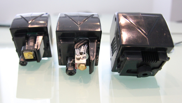

Printing Head V2.

IMG_20151008_121437

The Standard duty printing head will be the Print Head V2 (while officially this is the first “print only”, it includes all the knowledge from V1.)

  • Totally serviceable with heating cartridge.
  • Print PLA, ABS, NYLON, HIPS, PC and PETG.
  • Additional cooling fan
  • will reach higher temperatures (250°-260°) in continuos operation with fan always on.
  • full metal body, can survive cartridge overheats.
  • inox steel melting chamber, with heatbreak to stop thermal flow to the head. This, again, will get you a more resistant head, which will endure longer and will stay clean and safe from damages.
  • Aluminium heat sink to cooldown the body and PTFE liner.
  • Brass nozzles will be interchangeables. standard nozzle: 0.4mm.
  • Due to the geoometry of the heating chamber, overhangs and bridges are less of a problem now: Less friction allow better retracts wich means better flux control and better prints.
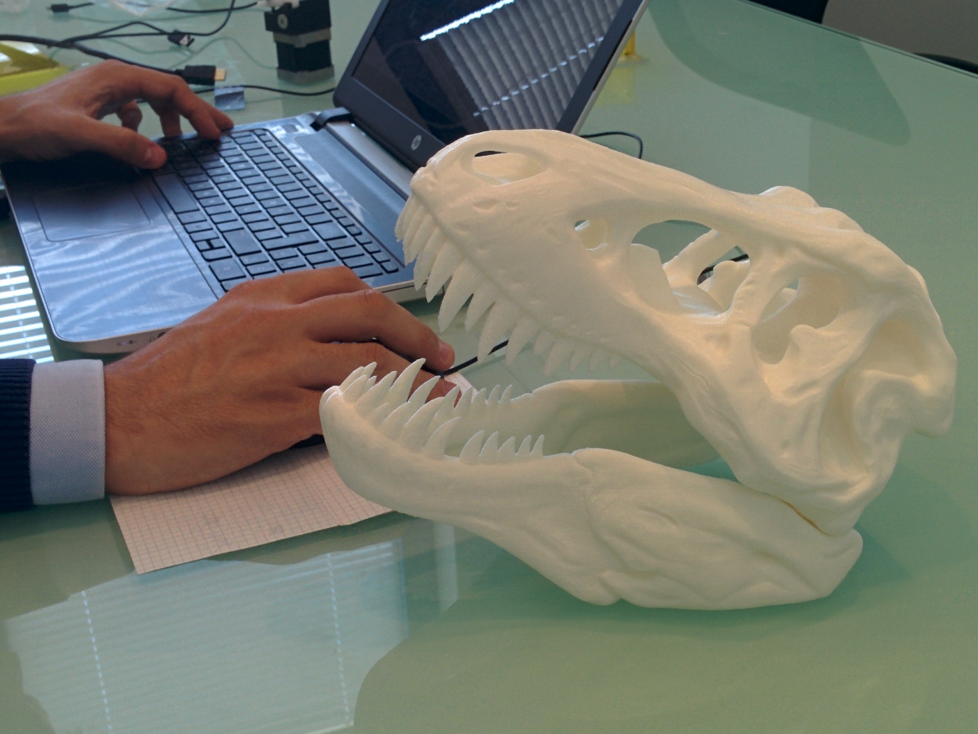
 

Milling Head V2
The new milling head is lighter and has optional vacuum support attachment that you can replicate with the FABtotum as well.
The new shaft has been balanced and less noise is now produced (sensibly less, you can actually speak fine in proximity of the FABtotum milling).
Splitting the motor from the printing side makes both easier to keep clean and safe from damages. Hot temperatures won’t get you any trouble.
the milling head V2 can be paired with a vacuum clip (taht you can print as well) to suck dust away.
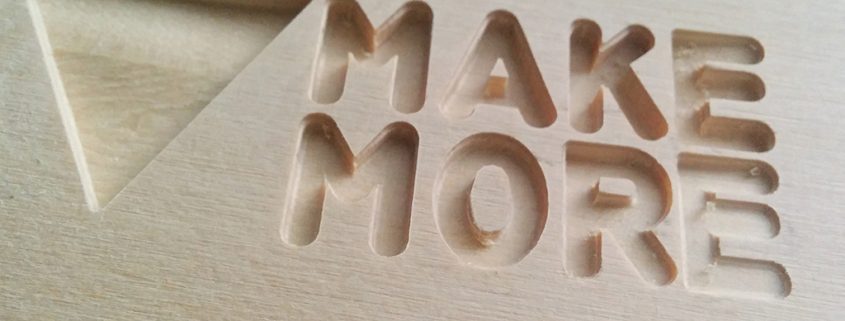
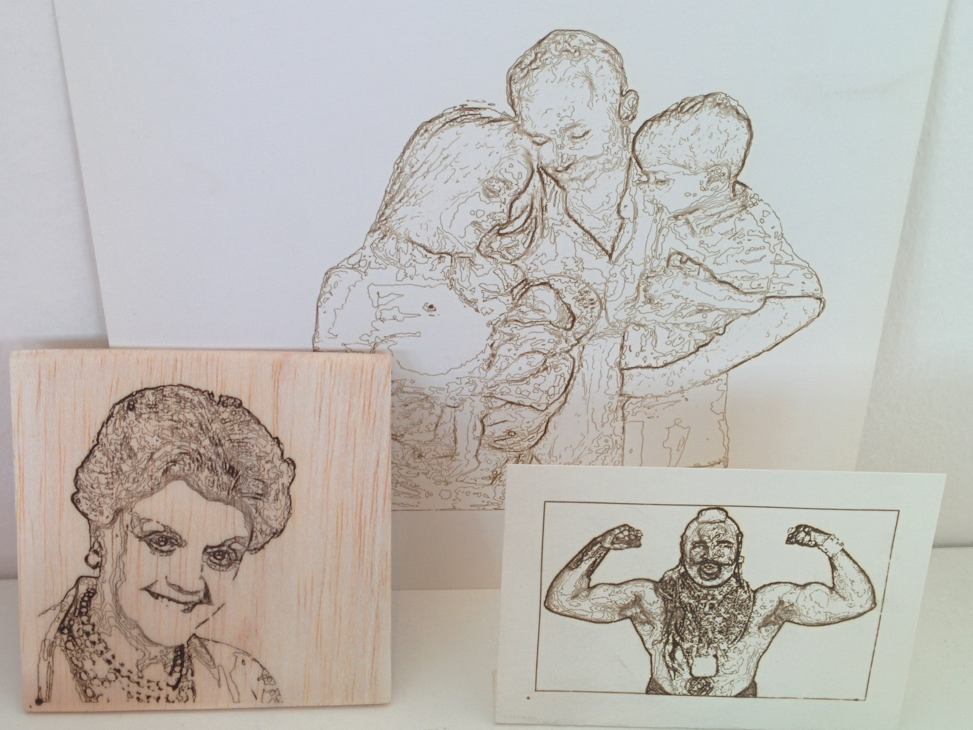
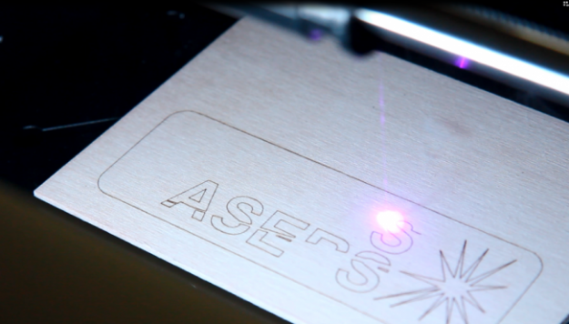
 

Laser Head V1
We’ve been working on our Laser Head for a while now.
I’ts a little cool 500mW (or possibly 1mW by the end of development) module.
There might be many uses in labs, PCB engraving and so on.
We’re looking at possible suggestions, so feel free to tell us what you would do with it.
In short, more than engraving we are looking at possible applications, we are running out of parent pictures and 80’s icons, you know.

IMG_20151008_121529
Some examples made with cura. other plotting methods are available.


Hybrid Plate V2

bed_preview_render

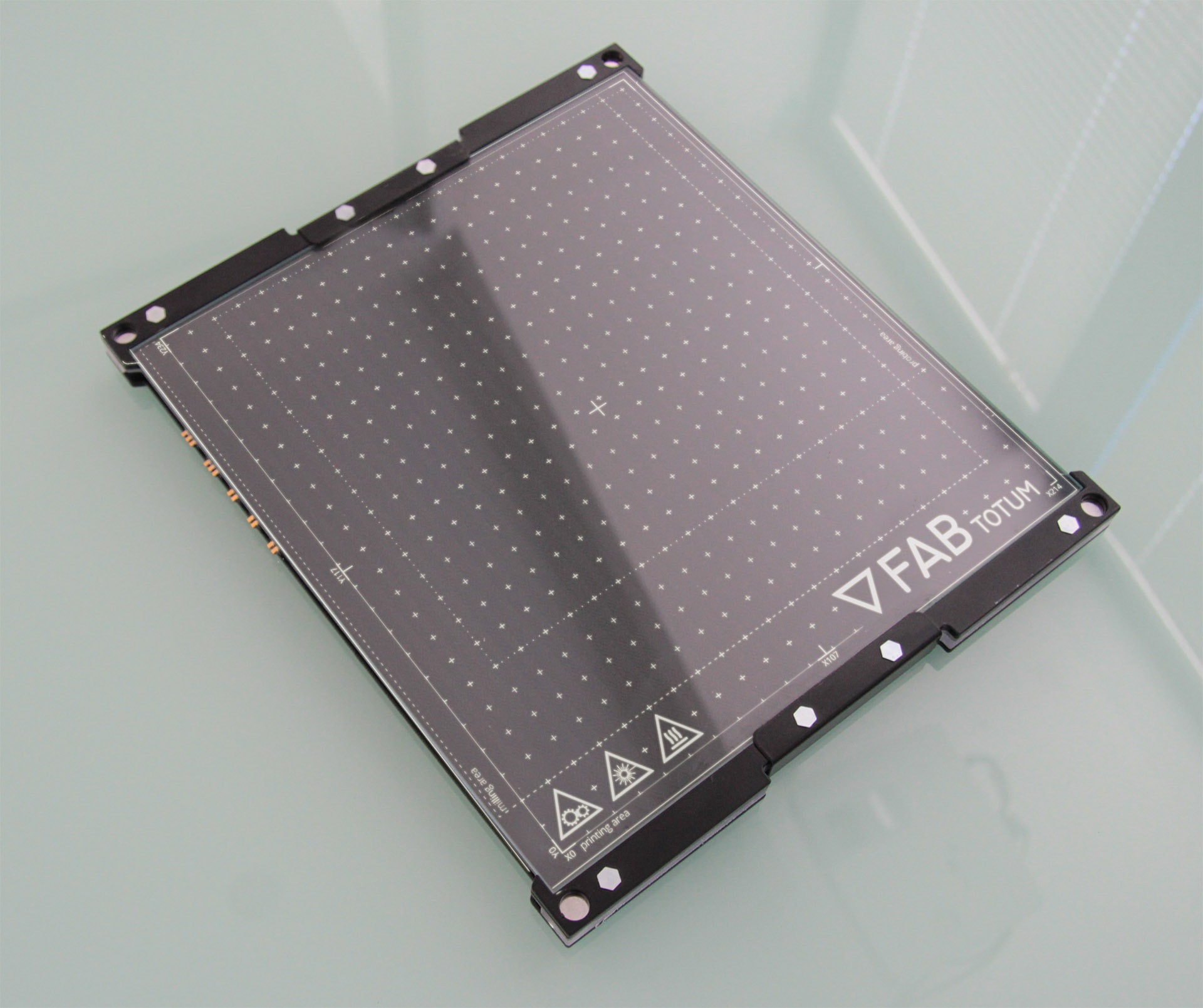
The Heated bed (as much as Hybrid head’s) design hasn’t changed much…apparently.
The design of the PCB has however moved to a more resilient solution that requires less “playing around” with the bed to get a stable electrical connection.
Heating is also much faster now, with around 1 minute less in heating time (around 1 minute to hit 50-60°C, good for PLA. You previously needed around 2 minutes with V1)
We added a new overlay for a better positioning of the parts. It’s a great help to know exactly where the print area is and where the milling area and the scanning area are.
The overlay grid in centimeters is a great help for quick measurements as well.
The Milling side hasn’t been changed as it has been proved effective.


The Hybrid Head is no more.
This has been a tough decision, but we are announcing the official death of the Hybrid Head.
The performances of the Print Head and the Milling Head are, compared to the Hybrid Head V1 and V2, on another level.
By separating the two functionalities we will be also able to provide tailored solutions where you can decide what head to purchase with the platform: new customers that are not into milling will be able to scrap an useless expense; people that do not fancy FDM 3D printing will be choosing milling and so on.
This concept will be further expanded with the introduction of the Laser Head and the PRISM platform…and what’s coming next!

This modular approach was always in the DNA of the FABtotum Personal Fabricator and will be pursued for the years to come. This is one of the keystones of this “PHASE 2”.
Providing a solid, high quality Printing Head and making it easy to service was the next logical step.

We’ll probably get some complaints for this unilateral decision, but we think this is for the best. As many suggested, there are technical and practical reasons to steer away from the Hybrid Head (which, by the way, was a great accomplishment technology-wise).

IMPORTANT! All existing Hybrid Head orders will be converted to Dedicated Print Heads and given either a free hi-quality spool or a partial or full refund for the order. The Hybrid Head is now officially discontinued. If you are in line for one of those you’ll receive an email notice in the next few days. All (and only) existing FABtotum orders will receive both a Printing Head and a Milling Head with no additional cost.

Switching to this new idea of a more personalized FABtotum will have its effects though: new parts are expected to be delivered us within November, which is slightly after our first estimate. We know these are bad news, but we’d rather delay than rush.
Keep an eye on further updates to make sure you are always aware of what we’re doing. We will of course alert all queued orders about the shipping times (of both heads and FABtotum).


We’re heading to Rome!

IMG_5296

“Rome wasn’t built in a day”: this turned out to be true for us as well. A year later we are back to our capital with an improved version of the product: we will be there to show you the progress made so far. We still have tons of things to do and to develop but as the ancients said: “All roads leads to Rome” so here we go!
If you get the chance to come, don’t miss our stand: as soon as we get to know our exact location in the faire we will inform you.

New filaments available

spool_PROMO

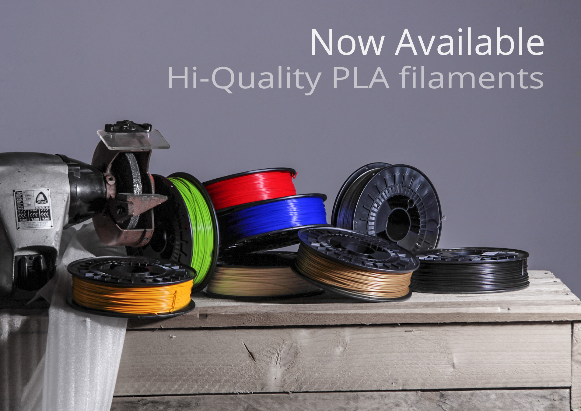
Following the high requests, we are glad to introduce our own line of filaments. These comes in convenient 750g spools that fits nicely in the FABtotum spool compartment. They are tested on our FABtotum of course, and are Made in Italy.
More colors and materials will be available in the future; right now you can already enjoy a color selection that ranges from “sun yellow” to “silver”.

Discover all the filaments here


New Support System in the works.
Assistance and Customer Care has been one of our weakness, we know it. Along with increasing our staff and have more people to assist you with any request (you are a growing community, we need to expand as well!), we are working on a different Ticket System which will get to a better assistance experience for both you and us. Also, we are about to add a range of FAQs which will be constantly updated in order to give you a first (and ready) answer. Our Wiki is always open to any review (we are thankful to all the users who help us!) so this is getting better as well. Along with all these updates to the FABtotum, we will rewrite the manual as well. This will be available online of course and we will update it when needed.

New Ticket System will be available for FABtotum owners only: a Product Code will be needed to access the system and get in touch with Support Team.
Tickets will only take care of Technical troubles while any other inquire will be addressed to an online form which will alert us via email and authomatically redirect it to the right person according to the selected subject.
Every customer will be followed by a single troubleshooting procedure from start to finish. We also streamlined replacement procedures. Communication between you and the Support Team will be easier, with a clear chronology.

IMG_20151009_145253


What’s next?
So far so good then, but we are not stopping yet. We are of course developing PRISM as well, and we wll update you all with a dedicated post as soon as possible.
Hoping to meet your expectations, we’ll be back soon with all the news we have!

Stay tuned
the FABteam

,

Sneak Preview: Hybrid Head V2, Laser Head and…

Best CNC and rapid prototyping materials: paper and cardboard

Hi everyone!

After a short break we are already back with some updates for you. Expect more in the near future, you’ll hear from us again really soon.
In the meantime we can tell you that, after two years from the start and one of production/deliveries, we have a bunch of new things that will be available in the upcoming days.

The Hybrid Head V2
We told you in the previous post that the Hybrid Head V2 is on its way: we’re not done yet with it though: we are still working on the last details; the final result will offer you the best performances ever and a better quality of prints.
While waiting for some smaller parts to be delivered and tested, we are already watching it printing fine objects.
In the picture below you can see some samples that show you the improvements: higher temperatures let us try different materials and we can proudly tell you we can print PLA, ABS and NYLON.

Samples of prints with the Hybrid Head V2

Samples of prints with the Hybrid Head V2

The specs are the ones previously released but we take the chance to sum them up:

  • full metal body hotend;
  • improved fans system;
  • completely interchangeable nozzle (which means easier maintenance/replacing);
  • completely interchangeable cartridge;
  • different nozzle sizes available (we will tell you more later on);
  • 260° max working temperature.
First pictures of the Hybrid Head V2: final look may still change

First pictures of the Hybrid Head V2: final look may still change


A new Feeder
The feeder mechanism has now become simpler and does not require any action to switch between additive and subtractive mode.
No more buttons to be pushed: new FABtotums will have a slightly different feeder and won’t have any hole on the back inner panel.

What if you already have a FABtotum and want this to be available on yours as well?
We will add a dedicated note on our wiki as you need to manually change it before switching to the new version from the settings of the FabUI.
This is something we decided to change as a consequence of the community’s experience. That’s why, once again, we are always looking for your feedback.

Scanning update
Out of the three first capabilities of the FABtotum, scanning option has always been difficult to be used. Results were not always reliable and satisfying. We worked hard on this as we wanted to offer you a better product. In the upcoming months we will focus even more to have you less stressed when postprocessing. Shapes will be less deformed, the camera is going to add colours and details to the final result. We will tell you more as soon as we have news and we will always update our development log on the forum as well.

Developing the scanner results

Developing the scanner results


A more complete Wiki
First year of FABtotum’s life also gave us a better idea of which were the main obstacles between a bad print and a good one: 3d printing can require a bit of knowledge first and our machine as well need to be “discovered”.

To help you (and to help us as well) we are little by little completing the wiki: a lot of new contents have been added every now and then and still are. Our Team together with the community increased the literature available online so that troubleshooting and first steps became easier.
You can give it a look and find out yourself here


An idea of all the components of the FABtotum

An idea of all the components of the FABtotum

All the documents are now on GitHub
We have gone even further than that: loyal to our Open Source identity, on Git Hub we added every missing specification. From hardware (already available on GrabCAD) to software, everyone can see what the FABtotum is made of and how it works. Suggestions are appreciated, simple curiosity is also welcome.
Here is where you can find everything

Laser Head
It has been in our projects since the beginning and it is now pretty much ready. We are still testing it, but the first results have seen our smiles rising and shining on our faces. It is not mentioned to cut hard and thick materials: we still prefer to leave this kind of job to the milling motor. Now you can throw away that smelly mutated seabass of yours.
With the laser head of the FABtotum you can:

  • engrave woods, plastics etc;
  • cut thin sheets of paper, cardboard and plastic.

You cannot:

  • cut thick plastics or other thick materials (>0.2mm)
  • pretend to be an evil scientist.
Testing the laser precision and quality

Testing the laser precision and quality

The new head won’t replicate the capability of the milling head. However, as you may know, laser engraving has a much more higher precision. You will be able to write or draw lines on the mentioned materials, as well as cut what would be too soft of thin for a drill bit.
The power of the laser we will use is 500 mW: nothing too powerful, just enough to do what’s needed.
This means that it won’t be too dangerous or require special equipments, but it will still be better to use a bit of extra care when turned on.
This is how it will look like, more or less:

First pictures of the Laser Head - final look may be slightly different

First pictures of the Laser Head – final look may be slightly different


It will be easy to be mounted on the FABtotum and won’t require extra calibrations in addition to the ones you would normally do.

Coming soon…
Today, then, we can say we already pushed the envelope a bit further than the first idea of FABtotum, born two years ago on Indiegogo.

The three Heads: the V1, the V2 and the Laser Head

The three Heads: the V1, the V2 and the Laser Head

But, as said at the very beginning of this post, we still have other great news coming soon…

teaser

Keep following us!


*Available from next release, due on 20th August.

,

Development & Production update

Hi Everyone,
Here we are, back with another update.
Today we’ll be focusing on production and future plans.

But first lets start off with a little goal: we just surpassed the number of 400 FABtotum delivedered! Yay! In around one month we will have delivered all the Indiegogo units and we will start shipping the ones that have been purchased from our store. If you were among those of the first and second batch and you didn’t hear from us yet, please consider to write an email or check that the order page has been filled completely.

Production capability
During the last couple of months we promised to have a faster production rate to reduce delays. We weren’t able to keep that promise.
Considering the feedback collected we worked (and still are working to this date) in order to solve the reported issues.
As a result sometimes we have to wait newer components, we have to test a particular solution on the assembly line etc. For this reason from time to time you’ll see a slow down in production.
There is no need to worry, as this mean we are actively investing time in improving the device and ironing out usability and reliability issues for a limited period of time.

Development Activities
The FABtotum has been released just a few months ago, but this does not means the development process has stopped.
It is in fact more active then ever on many aspects of the machine.
To better keep track of it and report the direction in wich we are going, we redacted the Development Document for early 2015 activities.
The document focuses on user feedbacks, features we want to add and issues that required attention (and how we think we solved them)
If you are into community development, this is for you.
Last month the mechanical drawnings have been published over Grabcad.
Open source documentation of the project is growing month after month, and many projects have spurred around that.
We would like to to thank all the people who help us growing and share their ideas/projects as well!

Shows // Meet FABtotum
The FABtotum P.F. is travelling all around the world, so do we!
Starting with 3D Print Hub in Milan, then 3D print Show in Berlin and finally the LA Maker Faire, this spring we will be travelling a lot!
Make sure to drop by to meet us and the FABtotum Personal Fabricator!

Updates
From today we will start to do updates that will be posted on both the blog and the Indiegogo activity page when needed, so be sure to check both!

FABteam

, ,

FAB UI, the FABtotum user interface.

A while ago we talked about the FABtotum User Interface. Today we’re back on the topic to discuss some of the features of the FAB UI.
You may have seen many 3d printers web interfaces, but how many multipurpose personal fabrication user interfaces? None? so did we before starting this project.

In the Alpha version of the personal fabricator there was simply no user interface. to print you had to rely on external software like Pronterface to print, a processing script to scan on the PC.
The main challenge we faced with defining the FAB UI was to answer the following questions:

  • How do you provide a integrated panel to assist you seamlessly during all the personal fabrication process?
  • How do you do that without making the interface too complex or alienating the user?

FAB UISetup Wizard
Once the FABtotum starts for the first time, the user is asked to set it up selecting a wifi network, user & password, and other things.
The informations provided (like email, user etc) are saved locally on the FABtotum SD card and are used to identify the owner.The email in particular will come handy in future updates.

User Login
A log in is required for safety and security purposes.
Safety because someone in your network could just access, push a botton and crush your hand while you are adjusting an object to scan in another room, Security because your local file database, as well as your informations or projects should not be shared unless you want to.
This makes also perfect sense if you think about connecting the FABtotum to the internet and allowing remote logins.

The Dashboard
The Dashboard is the first page you see after loggin in.
Current tasks and previous ones are saved here. The dashboard can be costumized by changing the position of the tables. Plugins (see below) can alter or add elements to the dashboard as well. Right now we are sticking to the “less is more” principle, but you might as well fill the page with everything you have or you develop later.

Scan
The scan menu is actually a section of the UI where you can select more than one scanning method. you can find some insights of those methods here.
As you can see each process is guided in a wizard-like procedure, wich has been chosen because it can break up the informations needed in multiple tabs, without flooding the screen with informations.

for example the scan quality (wich is determined by the camera resolution, numbero of points collected and postprocesses used) as well as the scanned area, can be selected with draggable controls.

A rubber duck is used to show the differences between the various settings.

Create / Print
The create menu is directly connected with the object manager (see below) to be able to print or mill directly from the available objects you saved.
You basically select the compatible files and click next.
Before printing you are prompted with some info (depending on the situation) and tips on how to better print or mill.
During the print process the user can override speed and temperature, while keeping an eye on the process.

Once the process is started some functions will be locked (for example you won’t be able to jog or make scans, but you’ll be able to browse the library.)
Thanks to this approach you may as well launch the print from your desktop PC and then log in the UI with a tablet and follow the print up close, like we did during the tests of the beta prototype. This is also true for remote access (connected to the UI over Internet).

Jog
The jog feature is a must have in each and every CNC machine, to position the machine and do manual operations. The Jog in the FABtotum supports both additive and subtractive machining, allowing to switch from additive to subtractive (A/E). The Jog interface can be costumized easily.

Object Manager (aka Object library)
This is where things gets interesting.
You can “upload” from the client (your browser) or from a USB stick the supported files.
In the FAB UI one “object” is not “one object”. Let me explain:
You scan an object using the rotating laser scanner. you get a point cloud file. but the thing has holes because of the limits of that particular scanning method.
You go back and do another scan with, say, the Z-probe.
You now have 2 clouds. If the points are enought to reconstruct the object you can go ahead, otherwise you can reiterate this process.
Once you are done you’ll have, let’s say, 3 ASC cloud files.
From the Object manager you can join those parts and obtain the complete point cloud.
Once you have that you may download it from your browser, or try to reconstruct it onboard (experimental/WIP feature). either way you obtain an STL.
Now you have 1 cloud file and one STL.

You can slice it directly on the FABtotum (experimental/WIP feature)  and obtain a G-CODE.
Let’s suppose that your object is made of more parts, and some of them are not made with 3d printing, but with the built-in milling motor of the standard-issue hybrid head.
You can add another GCODE to the “object”.
Or you may add another STL to slice and obtain all the parts needed.
Or you might want to run the mesh recontruction on a good PC to increase the quality of the scanned data. Guess what? you still have the raw point cloud to download and process!
The result, as you can see, is that the user doesn’t need to mentally switch from additive to subtractive or “plan” too much, and will be prompted by the interface to perform manual operations before starting different procedures if needed.

Plugins
Since the FABtotum can be used for many purposes other than the ones natively supported, one of the objectives of the development of this interface was to allow costumization where it made sense.
Plugins can be developed as an easy way to add functionalities to the interface and the device without introducing changes on the interface structure.
This way each plugin can be shared across all FABtotum users easily.
One plugin, for example, would allow STL or Gcode previews during the “create” process, something that required some external software.
We demoed this concept with the excellent Gcodeviewer by Joshua Parker.

We expect to see many great plugins from the community and we are planning to host those and allow direct download and installation directly from the interface (CMS-style).

Settings
In the settings page you can decide how the the FABtotum and the interface behaves.
Some of the settings are about the the device, others are about the appeareance of the UI.
one example is chainging the skin/theme of the UI, the other is setting the lights inside the working volume, directly changing the RGB values.
In the settings we plan to add diagnostic tools (like a “self test”), or a cleaning wizard, a leveling wizard, or a spool change procedure, etc (not showed here).

We also have python running in the shadows, provinding that middle level of interaction between the UI and the Firmware (see development update 4 on IGG).
This is used for example, to give the user access to a python script running at boot, wich runs with root privileges and can be used for a lot of things. Really lots. of . things.

Updater
On the FABtotum UI you can always check the latest updates available from the FAbtotum server. The update process is guided and automated both for the UI and the Firmware itself.
Those updates (I won’t stop to underline this) are not mandatory, they are just suggested by the UI since we plan to improve the interface further and eventually fix whats breaks in the process.
The updater notifies the user in the top left corner (the blue zero means no update has been found due to lack of internet connectivity).

Open source development:
Speaking of updates, the software sources will be online on GitHub under the Creative Commons Attribution-Noncommercial-Sharealike 3.0 Unported Licence, when ready. contributions will be integrated in the stable version and released for everyone.
Same goes for the firmware!

Belts and stuff: experiences to share.

We are finally back with an insanely long Blog Update!

With the FABtotum Personal Fabricator we went through a series of experiences in designing a proper belt system, and we thought it might be cool to share this experience.
Some designs spawned several prototypes, some of those where a step forward, other a failure, but all helped us progress to today’s development stage.
Here a bit of the story.

When dealing with hybrid machining you face a serious limit: provide fast movements and high accelerations (especially the latter) for additive fabrication and, at the same time, be able to have a very high inertia or pure “strenght” during cutting and milling operations.
For compact sized hybrid devices the answer has been in introducing new belt designs to keep forces under control and provide fast movements if necessary.

The first attempt can be seen in the Alpha prototype.
The Alpha Belt system was a modified carthesian one.
This version was the starting point in trying to mix subtractive and additive fabrication with a belt design.
In this version the Y axis motor drives a long belt that goes around the building space.
The X axis motor moves the head carriage with a normal belt. The best thing about this design was inertia and stability, but acceleration and noise was pretty high, due to a custom double-sided T5 belt.
The belt tensioning had to be perfect and the circuit was split in 2, so you had to manually balance the tension and try it a couple of times before getting it right.
It wasn’t the fastest and the strongest belt driven system but it could get the job done.

The system itself can be simplified as follows:

With respect to a simple cartesian motion in which each motor has his own belt and axis, the above design is more balanced, so that any force on the gantry is supported by an opposing force each time, easpecially when moving and cutting near the borders of the working plane.
From a mathematical point of view, however, the forces can be calculated easily as any cartesian system (0.5 Nm Nema17 motors have been used to fill the variables)


Eventually, we moved to evaluate a variant, in wich the Y belt was connected to the other side of the Y bridge.
This was a intresting concept that, however, had a flaw: space consumption!
The Y axis (moved by the blue belt) runs around the structure,
The next major attempt in improving hybrid manufacturing was during early alpha, with the HBOT design.

The Hbot design, like the CoreXY (of wich we’ll talk in the next paragraph) uses 2 motors connected to a single belt.

The system works like a ship pulley (or “block”) where the force is split in half. In fact it works like a 2:1 reduction.
You don’t need to lift the W weight, but only half of that, because your movement is reduced by a factor of 2.

In an H-bot or CoreXY system the X or Y movements are basically a sum of 45 degrees vectors. We are effectively working on a tilted reference cartesian chart here.
Since vectors add to one another the resulting force in the normal XY plane is much higher. Sounds complex? here a scheme:


As you can see, with the same motors you get a different result than the basic cartesian system, with twice as much force in each direction (except in diagonal moves, ergo in the direction of the native tilted reference cartesian system). The price to pay is the distance you move, wich is effectively reduced to half, just as expected.

This alternative driving method was simple and effective in most movements and condition but one: X-axis movements. To fight the movement on the Carriage, forces have to be balanced properly. If the XY carriage faces resistance (like in any machining), there is a resulting force in the gantry that causes the gantry itself to flex, generating positioning errors.
This is pretty clear if you think of “what is holding what” and looking at the gantry.
The Hbot design can bring substantial advantages during additive manufacturing but it’s not suitable for subtractive machining due to this problem.

To balance the forces in a belt driven design, systems like the MIT’s Core XY have been developed, and we did some research too to see if it could fit our application.


From a movement point of view the COREXY can be summed up as a normal cartesian motion tilted on a 45 degrees angle, just like the simpler H-Bot (see http://corexy.com/theory.html).

Unlike the H-bot, however, the CoreXY introduced a crossed belt that balances the forces on the gantry. From this basic implementation the COREXY is a valid hybrid system that however has some flaws.
First and foremost, the belt is very long, introducing a “dampening effect” due to the belt extending under tension.

One solution is the one to increase the belt size, but this means more friction, noise and loss in force in a system with 8 idlers and 2 motor pulleys for a total of 8 90°angle turns and 2 180° angle turns.

Never cross the belts
Try to imagine all life as you know it stopping instantaneously and every molecule in your body exploding at the speed of light. Ok it’s not going to happen but that’s what you’d deserve for driving belts that way.
Belts in the coreXY are not running on the same plane because they have to cross on one side to balance forces. The result is that each tooth of the belt entering the pulley encounters a non-straight pulley, wich results in noise and possibly ruining the belt in the long term. We love the coreXY beacause it’s essentially a great and smart solution. Many things like belts crossing could still be improved in the FABtotum and so we started working on it tirelessly to squeeze each and every last Newton we could.

But before continuing let’s have a recap of some of the belt-driven systems we considered during the Alpha and Beta development.
Our interpretation of the Core XY solution was to avoid crossing the belts, like in a H-bot style design, but still having the advantage of balanced forces of the Core XY design.
The solution we adopted was to have 2 closed belt loops, on two different planes.


This way effectively compensates the Hbot torque on the gantry with the help of the belt on the other side. At the same time avoids unortodox pulley mis-usages.
The system works like this:

M1, the left motor, drives the red circuit, while M2 drives the blue circuit.

Those 2 belt circuits run each one on different levels, always straight and do not cross.
Two equal and opposite forces “F” separated by a L distance generate a torque of M=2FL.
In this solution the forces generate a couple on the carriage, wich is effectively mitigated by the short distance between the 2 forces.
If we compare this to the Hbot, we basically moved the problem in a location where it couldn’t affect the system anymore.
In other words, while in the Hbot “L” was really big (the distance between the motors) now L is the distance between the 2 anchor points on the carriage/head wich can be as small as we want. 2F*(small L) = Small torque.


Of course this is just a part in the bigger game that is “making the thing faster,better,stronger”. Part of the improved machining capabilities can be traced in improved stepper power management, but also in a lighter carriage and moving parts.
Le’ts see more of that, shall we?

Structural superiority, part II

With the belt design out of the way, the mechanical team lead by FABtotum’ Chief Engineer Alfredo Marinucci started working on the improved structure for the Beta Version.
When we started the Indiegogo campaign we developed the simpler and most effective way of keeping things together, but thanks to the campaign’ success we could afford to be more bold, and to push the structure even further.

The pursuit of a good-looking, solid, simple and reliable structure is the main problem of any design endeavour, and this was also true with the FABtotum’ structural outer shell.
Italian Design is well known to have never turned down this challenge before, from the field of engineering to pure aesthetics choices.
With the design process of the outer shell we went from a flat design that was a mere accessory made in a single material, to a complex and reliable part.
The shell is made with a composite material: an fiber-enriched polymer, that is capable of withstanding more load than the previous one.


We didn’t have any prototype of the outer shell until last week, when we finalized the molds (see last IGG update). From then we were able to start building the pre-production prototype with the outer shell, covers, bells and whistles, instead of the “naked” prototype we showed recently. The company we are working with to produce these parts has a long history in automotive industry. The fact is that the new shells are in no way cheaper or weaker than the Alpha side panels, but they add a new level of reliability and quality to the FABtotum.
With Alfredo’s passion for automotive engineering and the materials used, you could as well compare the FABtotum’s structural shell to the 3d-printing industry equivalent supercar racing chassis.

Hybrid manufacturing
One of the most important parts of the hybrid manufacturing design is how you actually mill/cut in the end.
The FABtotum uses a 200W brushless motor with a custom made (and soon to be open source) ESC to pilot it. This setup has been proven solid and a definitive improvement over any other Beta prototype we tested, including AC spindles.

The chuck and the axle of the motor are machined for precision, but we have different suppliers with different specs to look into it as one of the last assignement in the development of the FABtotum Personal Fabricator.
Those are the last things we are deciding this month before ordering parts.

Overall, hybrid fabrication on the FABtotum is possible thanks to several solutions adopted.
From the alpha we where able to change many times our approach and end up with something unconventional but reliable.

As with the mechanics many things contribute to the effectiveness of this sub-assembly, like bearings, power control and cooling.

Closing words

This is it for today’s Dev Blog entry,
Hopefully we showed some light on the mechanical development process and how important it was to us, how much effort we put into it and why we think we did a good job.
We know there are loads of things you would like to know, and things are getting ready pretty fast. We ourself can’t keep track of the advancements.
Proof of that is this very post that has been postponed because it became obsolete in one week!


It has been a long way from that prototype (wich admittedly has been savaged for spare parts from time to time). While the time passed very fast, we can’t really make up our mind on the sheer number of things we investigated and tried before committing to a change.
With Indiegogo’s upcoming campaign update we plan to show the final pre-production prototype as we prepare to start manufacturing during April.

hold on until then!


related links
https://github.com/ErikZalm/Marlin/issues/463
http://www.edn.com/electronics-blogs/mechatronics-in-design/4368079/So-you-want-to-build-an-H-bot-
http://www.anthonyvh.com/2013/05/21/halubot-part-1/
http://www.cnczone.com/forums/diy_cnc_router_table_machines/51485-make_gantry_rock_solid.html
https://groups.google.com/forum/#!topic/h-bot-and-corexy-3d-printers/1gb6oo291zI


FABtotum Electronics in the wild.

fabtotum_board1As all computer-controlled devices, the FABtotum rely on electronics to perform all the operations needed, both from a computational and physical point of view (calculate what to do and correctly move motors accordingly).
In a CNC device, movement and I/O controls are an important part of the electronics design.

During the alpha development we used a RAMPS (an arduino Shield) mounted on an Arduino mega,a common setup for DIY 3d printers.
Like us, many people in the community enjoyed this kind of simple and convenient setup, where the instructions (in the form of GCODE language) are executed and the I/O managed from a single unit.

When we started the Indiegogo campaign we had no real need of changing that, but thanks to the feedback of the backers we set a goal to improve and push the envelope for this compartment in the FABtotum Personal Fabricator.
As you know the brain of the FABtotum is a Raspberry Pi Mod B, a hugely supported ARM-based single-board computer.
The raspi added a bunch of neat possibilities to further develop the FABtotum platform with the capability to run complex programs.

To move the motors, sense the environment and control heating, extrusion and machining you need what’s called a power control board.
We have one, connected to the Raspberry Pi via GPIO pins.
So, lets see the (yet unnamed) Arduino(TM) derivate board!

The board itself is not that bigger than the Rapberry itself, sporting a 92x85mm rectangular shape.
A good amount of time has been invested into optimize this, thanks to a 4-layer PCB design. This choice is not just for saving space,but to enhance power distribution on the board.

Power supply is a key element in controlling CNC applications and robotics, and there is a lot going on in terms of power management here.
First and foremost, the board is powered by a 24 volt power supply instead of the usual 12v.
This means less currents , less ohmic dispersions, thinner cables, faster stepper motors, more power to hotplate and heater. The board can supply the raspberry with the needed power from his own power supply, along with a integrated Raspberry Pi logic level interface circuit (+5V <-> +3.3V).

More power does not mean less safety: the board has been designed with advanced solutions to minimize potential damages to the unit and maximize his life under hard working conditions.

All power Outputs provide positive voltage instead of negative, for safety purpose , meaning that if an output is off, there is no voltage at all.
In the RAMPS design even if the negative output is off, the positive pole of a connector was still on, meaning bad things could happen.
More than that, power outputs are designed with inductive load protection, to avoid voltage spikes during turn offs that could damage the drivers.
On top of all this, we have an integrated sinked current acquisition and control
circuit that allows to check and manage power consumption of the board and the stepper
drivers, meaning that also motor tuning can be done digitally.

The board is, of course, a 5 (yes, FIVE) axis control board, with highly enhanced heat dissipation design on each of the five stepper drivers.

On the board we added many other utilities like buzzer for audio feedbacks as well as various RGB lights to make human interactions easier with the FABtotum Personal Fabricator.

From a developer standpoint, the onboard ATmega 1280 can be reprogrammed directly by the Raspberry Pi and the FABtotum web interface. This means that we’ll ship the electronics with a modified Marlin Firmware, and you’ll be able to update the FABtotum or edit the source file, compile and flash it from the web UI again without connecting anything or pushing reset bottons inside the case, neat uh?

If you are really into electronics and you cannot resist puttings your hands on it, we placed an informative silkscreen on top of the black layer. Some fiducial markers are there  for automatic population of the board, meaning that the board is ready for automated assembly with pick and place machines.

So, Looking at the board, you can recognize the following I/Os:

  • 16 poles – 4 axis connector
  • 5th axis on a 4pole JST connector PH series 2mm connector
  • Endstop n1
  • Raspi GPIO header connector
  • Hotbed connection
  • emergency switch
  • Case-door safety switch
  • Front door safety switch
  • YZ Endstops
  • 24 v Power supply
  • interior light output
  • Second Extruder temp
  • Head connector (this includes: Milling motor control, Extruder 1 heat control, Servo control, Servo powering, Laser control & power, Head light power, probe input,fan control and an I2C bus, X endstops, led controls.
  • Board Fan power

We hope you liked this update, hit the comment section in the forum and let us know what you think!

First Z-axis test assembly!

The first Z-Axis  test assembly was a success.
During the assembly process we learned so much more on the structure, leading to improvements on overall weight and build volume we plan to implement.
The quality of the build is what makes us really proud!Look at all that metal! sweet!
Other stuff we will do soon is creating building masks for easily placing the components before bolting them! We will implement and test those soon,along with other fast production tecniques that have been suggested!
Coming soon: Z- trasmission and stepper motor testing.Y and X axis are already assembled and ready to bolted on the frame, but we are testing the Z axis first because it’s the most crucial to print quality.

Everything is looking good so far, we will show more and more details, culminating in the final unveil of the machine.