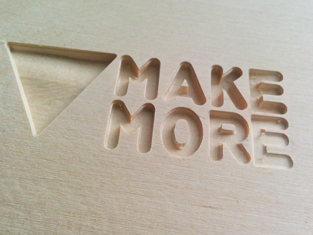
CNC Milling: Making a “Make More” Sign
In this guide we are going to take a step-by step approach on how to use the FABtotum for CNC milling, by engraving a sample sign.
We will engrave the “Make More” signon a foam stock block. We’ll use foam because we can avoid damages to the milling bit if something fails.
Files required:
You can download the SVG from which the gcode was created here: Makemore.svg
Download the .nc file (is the numerical control file): Makemore.nc
Preparing the Milling Job
- Turn upside down the Hybrid Bed so that it shows the milling side.
Do not mill on glass as it’s dangerous. - Place a piece of material that you will mill and fasten it to the bed (Using M4 Bolts and nuts or in this case two-sided duct tape as the material is very light). For this example, the dimensions have to be at least 135x55x20mm (about 5x2x1 inch).
- Remove the Hybrid Head or the Milling Head and using the provided tools to install the milling bit of your choice.
- Install the Head on the carriage and on FABUI.
- Upload the .nc file in “Project Manager”
- Now go to the Make Menu and start the job for the file you just uploaded to the FABUI.
- Mark the “Origin Point” with a pen on the stock material. The point mustn’t be exactly on the edge, but 3-4 mm centered. For future reference, the origin point is exactly the same point where the X,Y and Z axis values are 0 in the CAD model.
- By using the small Jog widget, move the x,y and z axis (move this axis slowly, by reducing the “feedrate” and the “Z step” to not damage the tip of the milling bit).
The tip has to be few microns from the stock material, to make a fine calibration you can use a piece of paper: position it over the stock material and start to raise the z axis slowly, start to move the paper until it is blocked between the tip and the stock material.
NOTICE: If the endtops get pressed click on the warning message “OK” and move the head by hand (If they remain pressed, the controls won’t work).
When the tip is in the correct position, set “Zero” by clicking on the central button, then press “Start” this will “Zero” the position of the tool so it will start according the CAD drawing and more precisely aligned to the stock as the CAM instructions (gcode) expects. - When you are done, press start and follow the on-screen instructions. Once the Job has started, the milling motor will power up and the milling process will begin in seconds.
Take your time to go around in the Control tabs and see the current speed and RPMs.
You can play around a bit if you are using Foam. Other materials will be way less permissive. - Wait for the milling process to end (less than 10 minutes). The milling bit will stop and you will be later be able to retrieve the piece.
Make your own designs
This was a simple introduction on 3D Milling.
To make more complex designs you can count on a wide array of third party CAD/CAM programs that are widely available and scalable between different sectors.
CAD and CAM design is a wide and deep topic that greatly depends on the software used. If you want to learn how to create your own machining Gcodes starting from your own CAD, look at your CAD/CAM software package and follow the CAD/CAM guidelines for the FABtotum Personal Fabricator.
You’ll be able to generate a gcode file (*.nc, *.gc, *.gcode) with the set of instructions needed to CNC Mill or Engrave your very own CAD design .
In the meantime, check some of the community guides and tutorials on the topic.


